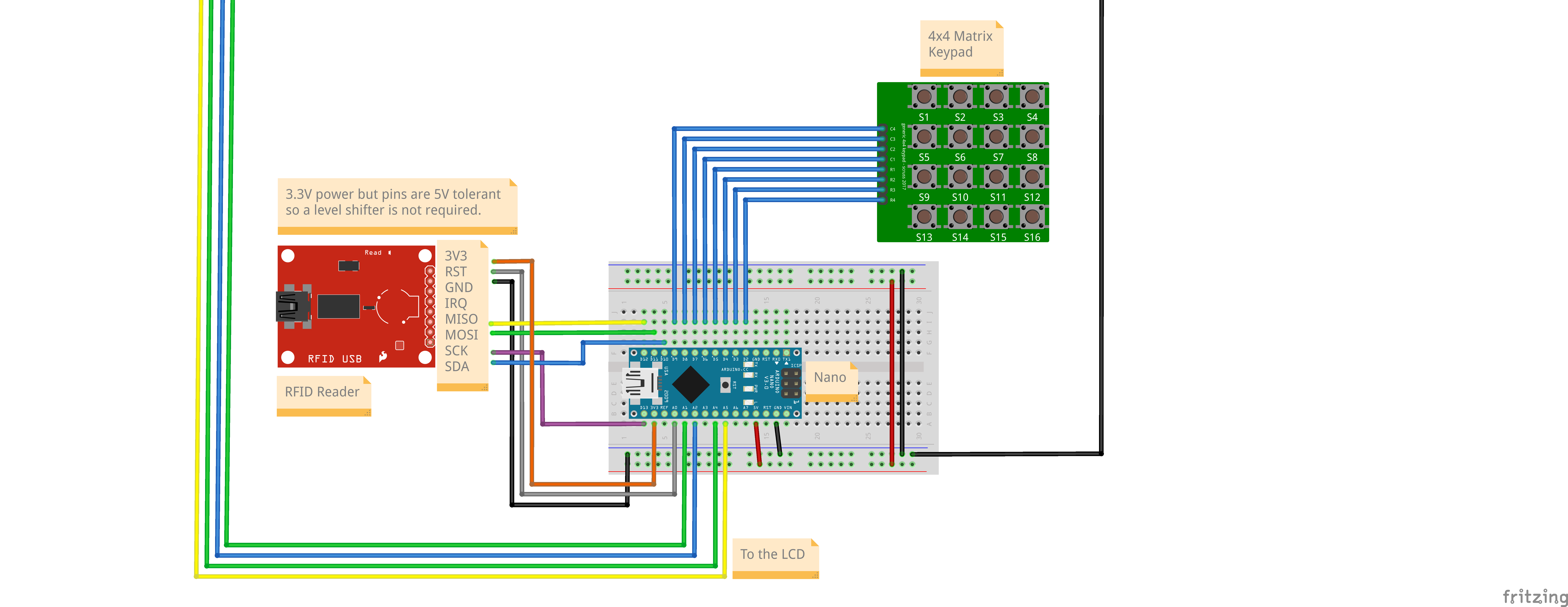
Nano Circuit 1 (Access Control Circuit)
This circuit will have a keypad and an RFID card reader connected to a Nano. The Nano will read the data and display it on the LCD, send it to the ESP32 over UART, and write the data to the default Serial port so that it can be read by the Node-RED flow.
Components
Note the component output is from the pin pov, needs to be mapped to the corresponding board pin.
| Component | Function | Voltage | Pins |
|---|---|---|---|
| Keypad | Input digits. | 5V | Digital Out |
| RFID Reader | Read RFID cards and tags. | 5V | SPI |
| I2C LCD 16x2 | To display data. | 5V | I2C |
| LED Module | Used as a visual indicator. | 3.3V | Digital Out |
Circuit Diagram

Connections
Board pin numbers are those printed on the board while code pin numbers need to be used in code (generally indicated in the pinout diagram as the GPIO pin number). They may be the same or different, depending on the board.
Board Pin | Code Pin | Pin Mode | Component | Pin |
|---|---|---|---|---|
| D2 | 2 | Digital In | Keypad | R4 |
| D3 | 3 | Digital In | Keypad | R3 |
| D4 | 4 | Digital In | Keypad | R2 |
| D5 | 5 | Digital In | Keypad | R1 |
| D6 | 6 | Digital In | Keypad | C1 |
| D7 | 7 | Digital In | Keypad | C2 |
| D8 | 8 | Digital In | Keypad | C3 |
| D9 | 9 | Digital In | Keypad | C4 |
| D10 | 10 | SPI CS | RFID Reader | SDA |
| D11 | 11 | SPI COPI | RFID Reader | COPI |
| D12 | 12 | SPI CIPO | RFID Reader | CIPO |
| D13 | 13 | SPI SCK | RFID Reader | SCK |
| A0 | A0 | Digital Out | RFID Reader | RST |
| A1 | A1 | Software UART RX | ESP32 | 13 (TX1) |
| A2 | A2 | Software UART TX | ESP32 | 14 (RX1) |
| A3 | A3 | Analog In | - | - |
| A4 | A4 | I2C SDA | I2C lCD | SDA |
| A5 | A5 | I2C SCL | I2C LCD | SCL |
| A6 | A6 | Analog In | Green LED | Anode |
| A7 | A7 | Analog In | Blue LED | Anode |
Code
The code for this circuit is distributed across multiple files, so will not be displayed here. It will be available for download for subscribers.