Arduino Nano
| Output Voltage | Operating Voltage | Maximum Current | WiFi | BLE | USB Connector |
|---|---|---|---|---|---|
5V 3.3V | 5V | Mini USB |
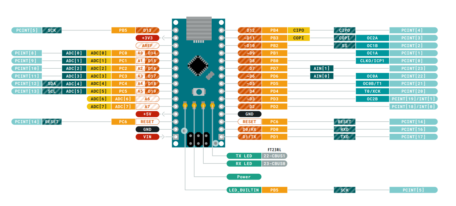
Detailed Pinout

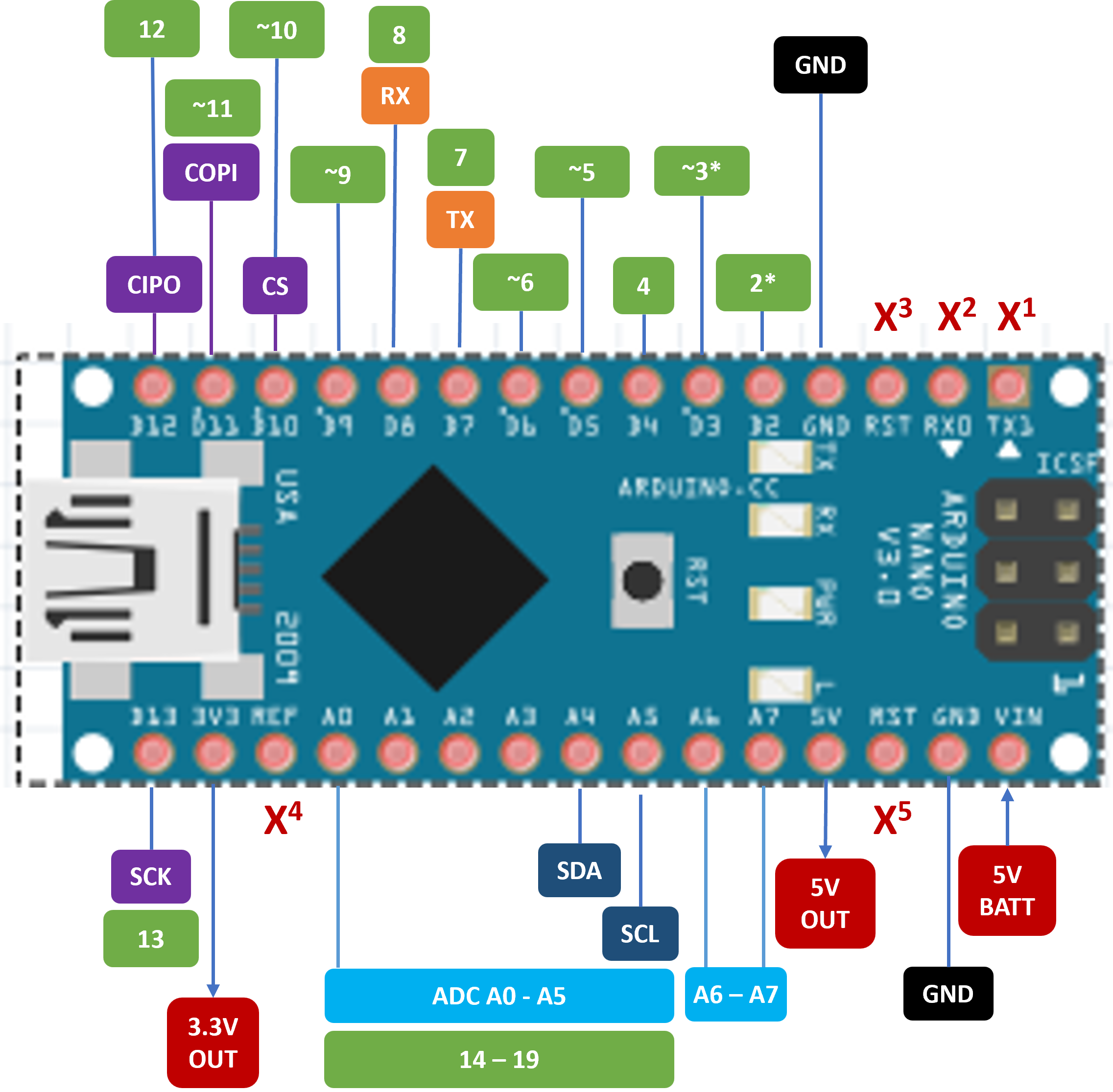
Simplified Pinout

Notes:
- Pins in green are digital GPIO pins.
- Pins in blue marked ADC are analog input pins.
- Pins in orange are for Software Serial UART.
- I2C and SPI pins are named accordingly.
- The primary pin function is indicated closest to the board, secondary functions going outwards. If the pin is not required for the primary function it can be used for the secondary function.
- Pin numbers shown are to be used in code. They may be different from the numbers printed on the board.
- The ~ prefix for a GPIO indicates PWM support.
- The * suffix for a GPIO indicates Interrupt support.
- Do not use the pins marked with an X:
- X1 and X2: Hardware UART TX and RX pins.
- X3 and X5: Reset pins.
- X4: Reference voltage pin.
Pin Functions
| Board # | Code # | Preferred Function | Alternate Functions |
|---|---|---|---|
| TX1 | 0 | Board UART TX | DO NOT USE |
| RX0 | 1 | Board UART RX | DO NOT USE |
| D2 | 2 | Digital GPIO | Interrupt |
| D3 | 3 | Digital GPIO | PWM / Interrupt |
| D4 | 4 | Digital GPIO | - |
| D5 | 5 | Digital GPIO | PWM |
| D6 | 6 | Digital GPIO | PWM |
| D7 | 7 | Software UART TX | Digital GPIO |
| D8 | 8 | Software UART RX | Digital GPIO |
| D9 | 9 | Digital GPIO | PWM |
| D10 | 10 | SPI CS | Digital GPIO / PWM |
| D11 | 11 | SPI COPI | Digital GPIO / PWM |
| D12 | 12 | SPI CIPO | Digital GPIO |
| D13 | 13 | SPI SCK | Digital GPIO |
| A0 | A0 | Analog In | Digital GPIO (14) |
| A1 | A1 | Analog In | Digital GPIO (15) |
| A2 | A2 | Analog In | Digital GPIO (16) |
| A3 | A3 | Analog In | Digital GPIO (17) |
| A4 | A4 | I2C SDA | Analog In / Digital GPIO (18) |
| A5 | A5 | I2C SCL | Analog In / Digital GPIO (19) |
| A6 | A6 | Analog In | - |
| A7 | A7 | Analog In | - |