Overview
This project reads values from MPU6050 sensor and displays the readings on a 20x4 LCD screen with an I2C backpack. There are two sketches which measures and prints the following parameters: The following values are read and displayed:
- yaw
- pitch
- roll
Components
| Component | Purpose |
|---|---|
| Arduino Nano | This will be the microcontroller |
| MPU6050 | This will be the Accelerometer |
| I2C LCD 20X4 | This will be the LCD display |
Circuit Diagram
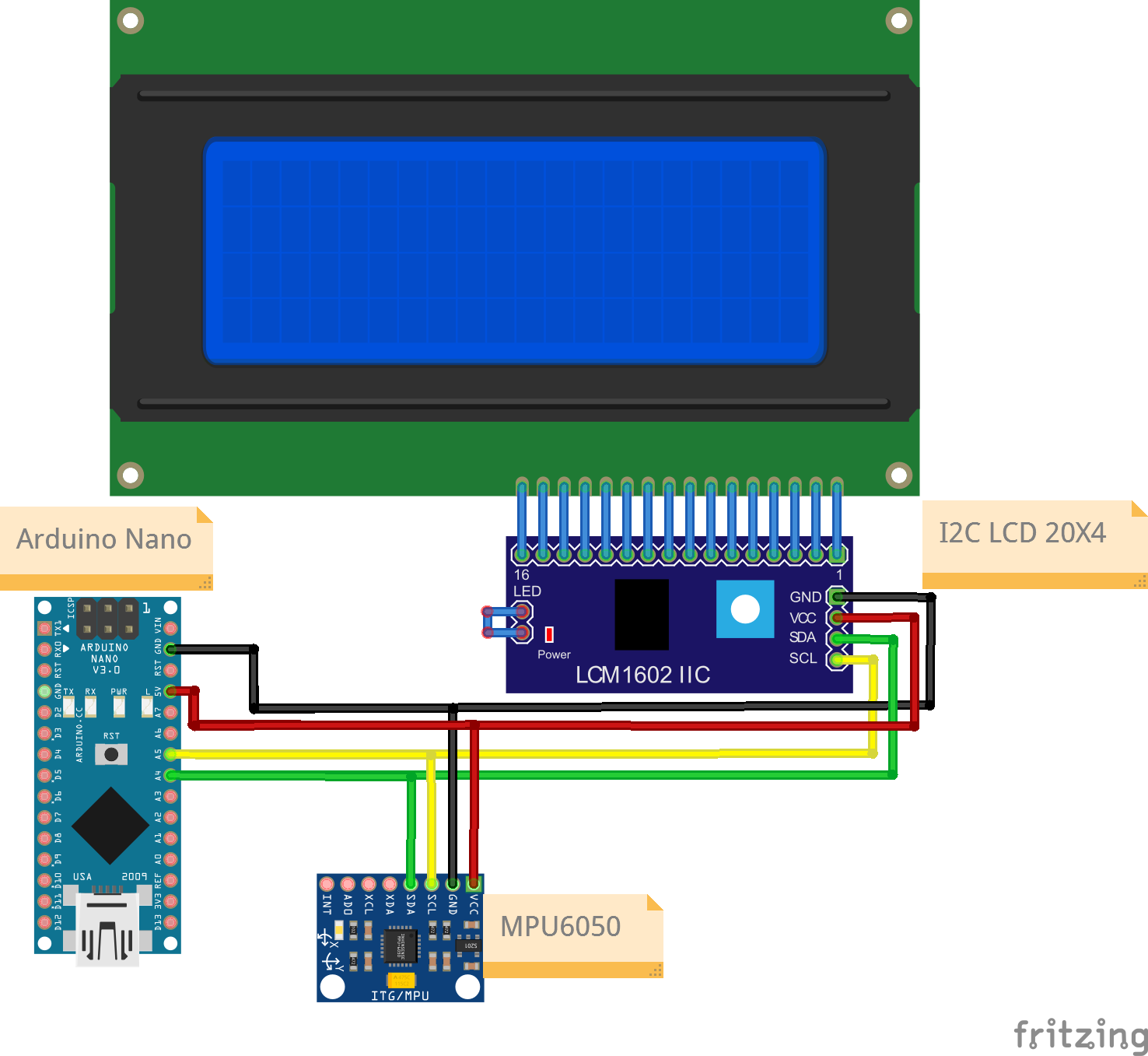
Connections
MPU5050
| Nano Pin | MPU5050 Pin |
|---|---|
| A4 | SDA |
| A5 | SCL |
| 5V | VCC |
| Gnd | Gnd |
I2C LCD Pin
| Nano Pin | I2C LCD Pin |
|---|---|
| A4 | SDA |
| A5 | SCL |
| 5V | VCC |
| GND | GND |
Code
/*
  Project: MPU Sensor value reading with output on LCD with I2C Backpack
  Project Description:
  This sketch writes YPR readings read from a MPU sensor to an LCD display module.
  This sketch is for a 20x4 screen.

  Author: STEMVentor Educonsulting

  This code is copyrighted. Please do not reuse or share for any purpose other than for learning with subscribed STEMVentor programs.
  This code is for educational purposes only and is not for production use.
*/

// LIBRARIES

//used for communicating with I2C devices
#include <Wire.h>
//to read values from the MPU6050 sensor
#include "MPU6050_6Axis_MotionApps20.h"
//https://www.arduino.cc/reference/en/libraries/liquidcrystal-i2c/
// Install the LiquidCrystal I2C by Frank de Brabander from the IDE library manager.
#include <LiquidCrystal_I2C.h>


// PIN DEFINITIONS

// GLOBAL VARIABLES
// Define the display size
const byte rows = 4;
const byte cols = 20;

// Used for reading a values.
float yawValue;
float pitchValue;
float rollValue;

//used to make lcd string
String yawString;
String pitchString;
String rollString;


/* INITIALIZE OBJECTS
 * Libraries usually follow an object-oriented approach that requires
 * an instance of the class to call its methods.
 */
/*
 * All I2C components have an address, the default is usually 0x27
 * If that doesn't work, see this:https://playground.arduino.cc/Main/I2cScanner/
 * The init statement accepts the address and the number of columns and rows.
 */
LiquidCrystal_I2C lcd(0x27, cols, rows);
MPU6050 mpu;


//GLOBAL VARIABLE FOR MPU READINGS

// MPU control/status vars
bool dmpReady = false;  // set true if DMP init was successful
uint8_t devStatus;      // return status after each device operation (0 = success, !0 = error)
uint8_t fifoBuffer[64]; // FIFO storage buffer
Quaternion q;           // [w, x, y, z]         quaternion container
VectorFloat gravity;    // [x, y, z]            gravity vector
float ypr[3];           // [yaw, pitch, roll]   yaw/pitch/roll container and gravity vector


/* LOCAL FUNCTIONS */


void readMPUValue() //read MPU6050 value
{
// if programming failed, don't try to do anything
if (!dmpReady) return;
// read a packet from FIFO
if (mpu.dmpGetCurrentFIFOPacket(fifoBuffer)) { // Get the Latest packet
      // display Euler angles in degrees
      mpu.dmpGetQuaternion(&q, fifoBuffer);
      mpu.dmpGetGravity(&gravity, &q);
      mpu.dmpGetYawPitchRoll(ypr, &q, &gravity);
      yawValue = (ypr[0] * 180/M_PI);
      pitchValue = (ypr[1] * 180/M_PI);
      rollValue = (ypr[2] * 180/M_PI);
      yawString = "yaw : " + String(yawValue);
      pitchString = "pitch : " + String(pitchValue);
      rollString = "roll : " + String(rollValue);
      Serial.println(yawString);
      Serial.println(pitchString);
      Serial.println(rollString);

}

}

/*
  Function to print to LCD on a single row.
  Takes the row number and the text to display on that row (max 20 chars, rest will be truncated).
  The entire display is cleared if the clear_all flag is true, else only the row is cleared (the default).
 */
void printToLCDByRow(int row, String text, bool clear_all = false){
  const char* twenty_spaces = "                    ";

  if(clear_all){
    lcd.clear(); //clears the entire display
  }

  lcd.setCursor(0, row-1);
  lcd.print(twenty_spaces); //clears the row
  lcd.setCursor(0, row-1); //cursor has to be set again after printing spaces
  lcd.print(text);
}

/*
 Function to print to LCD across rows with each row having 20 chars.
 Messages can be a maximum of 20x4 chars, rest will betruncated.
 The entire display is cleared before printing the text.
 Test string of 20 char:
 12345678901234567890
 Test strings of 80 chars:
 12345678901234567890123456789012345678901234567890123456789012345678901234567890
 Lorem ipsum dolor sit amet, consectetur adipiscing elit. Donec varius est donec.

 */
void printToLCD(String text){
  lcd.clear(); //clears the entire display

  byte chars_remaining = text.length();
  byte char_from = 0;
  byte char_to = chars_remaining < cols ? text.length() : char_from + cols;
  byte row = 1;

  while(chars_remaining > 0){
    String line = text.substring(char_from, char_to);
    printToLCDByRow(row, line);

    chars_remaining = text.length() - char_to;
    char_from = char_to;
    char_to = chars_remaining < cols ? text.length() : char_from + cols;
    row++;
  }

  Serial.println("Data string has been displayed on LCD");
}

 // function to LCD setup
void lcdSetup()
{
  // Initializing wire
  Wire.begin();
  // Initialize the LCD.
  lcd.init();
  // Turn on the blacklight and print a message.
  lcd.backlight();
  // Use the function to display text on each line indiviudally.
  printToLCDByRow(1, "I2C LCD Ready!", true);
  printToLCDByRow(2, "Enter some text.", false);
  printToLCDByRow(3, "Max 80 characters.", false);
  printToLCDByRow(4, "For a 20x4 LCD.", false);
}

void MPUSetup()
{

  // join I2C bus (I2Cdev library doesn't do this automatically)
  #if I2CDEV_IMPLEMENTATION == I2CDEV_ARDUINO_WIRE
      Wire.begin();
      Wire.setClock(400000); // 400kHz I2C clock. Comment this line if having compilation difficulties
  #elif I2CDEV_IMPLEMENTATION == I2CDEV_BUILTIN_FASTWIRE
      Fastwire::setup(400, true);
  #endif

  // initialize device
  Serial.println(F("Initializing I2C devices..."));
  mpu.initialize();

  // verify connection
  // Serial.println(F("Testing device connections..."));
  // Serial.println(mpu.testConnection() ? F("MPU6050 connection successful") : F("MPU6050 connection failed"));

  // load and configure the DMP
  // Serial.println(F("Initializing DMP..."));
  devStatus = mpu.dmpInitialize();

  // supply your own gyro offsets here, scaled for min sensitivity
  mpu.setXGyroOffset(220);
  mpu.setYGyroOffset(76);
  mpu.setZGyroOffset(-85);
  mpu.setZAccelOffset(1788); // 1688 factory default for my test chip

  // // make sure it worked (returns 0 if so)
  if (devStatus == 0)
  {
      // Calibration Time: generate offsets and calibrate our MPU6050
      mpu.CalibrateAccel(6);
      mpu.CalibrateGyro(6);
      mpu.PrintActiveOffsets();
      // turn on the DMP, now that it's ready
      Serial.println(F("Enabling DMP..."));
      mpu.setDMPEnabled(true);

      //set our DMP Ready flag so the main loop() function knows it's okay to use it
      dmpReady = true;
  } else {
      // ERROR!
      // 1 = initial memory load failed
      // 2 = DMP configuration updates failed
      // (if it's going to break, usually the code will be 1)
      Serial.print(F("DMP Initialization failed (code "));
  }


}

/* SETUP CODE: runs once when the board starts up or resets */
void setup()
{
  // Start the serial communication with baud rate suitable for your components.
  Serial.begin(9600);
  lcdSetup();
  MPUSetup();
  Serial.println("The board is ready!");
}

/* MAIN LOOP: runs repeatedly at a very high frequency (1000s of times a second) */
void loop()
{
  delay(1000);
  readMPUValue();
  printToLCDByRow(1,yawString , true);
  printToLCDByRow(2,pitchString, false);
  printToLCDByRow(3,rollString, false);
}