Circuit Design
When you have an idea or a requirement for an electronic circuit, you need to first design it before you can assemble or fabricate it. There are several software design tools that not only will help you design your circuit but also test it by simulating various inputs and determining the output.
The process of designing a circuit involves understanding the functionality required from the circuit then connecting all the required components in a meaningful sequence and order so that they will work together to provide the desired functionality.
Electronic circuit design requires a clear understanding of all electronic components, how they function individually and how they connect and function interactively with each other, their power requirements, the voltage, and current through each component and the circuit as a whole.
While very basic circuits may be designed using individual components, most complex circuits are designed around ICs (Integrated Circuits). These are pre-designed circuits, performing some of the standard functionality, and they can be reused in circuit designs for custom functionality. ICs in the electronics design field can be considered the equivalent of libraries in the software design field.
Circuits have a logical and physical design.
-
In a logical design, the components use their functional specifications, power requirements, and their interconnections to achieve the desired functionality, which is defined. Today, logical design is often done using computer software that uses what is known as a hardware description language (HDL), a specialized computer language used to describe the structure and behavior of electronic circuits. Several software applications, known as electronic design automation (EDA) software, are available for designing electronic circuits. Since modern semiconductor chips can have billions of components, EDA software is essential for their design. The software not only allows the circuits to be designed but also allows their functionality to be simulated on a computer by providing a range of expected inputs and determining the outputs which can be verified against actual requirements. It saves designers' a lot of time in testing and verification, and also errors are caught early before significant time and efforts are invested in physical design.
-
In a physical design, the actual physical components are chosen based on size and form (discrete or integrated circuits), connection mechanisms, and power sources depending on where the circuits are needed to use. Sometimes, based on the physical design requirements, there may be a change required to the logical design as well. In case some connections are not possible with the available components. The physical design serves as the input for the actual assembly process of the circuit.
Circuit Diagrams
Electrical and electronic circuits can be complicated. A drawing with all the components in the circuit, and their connections with each other, makes it easy for everyone from designers to fabricators to understand the details of the circuit. Drawings for electronic circuits are called circuit diagrams, while drawings for electrical circuits are called wiring diagrams. Circuit diagrams use universally recognized symbols for all components of the circuit. While it is possible to draw simple circuit diagrams by hand, more complex diagrams are drawn using a software application.
There are multiple types of circuit diagrams:
- Breadboard Diagrams:
These illustrate how circuits can be assembled using a breadboard, allowing components to be easily pushed in, like Lego blocks. The components are usually represented by shapes that look like the actual component. These are used only by hobbyists for very simple circuits.
This is what a breadboard circuit diagram created using Fritzing looks like:

-
Schematic Diagrams:
These are representations of circuits using standard symbols rather than realistic pictures. Schematic diagrams use very limited graphics to keep the diagram as simple as possible since the circuits themselves can get very complicated, and the graphics should not add to that complexity. -
PCB Diagrams
These are representations of circuits that provide details of how they should be fabricated as a PCB (Printed Circuit Board) is the final assembled version of the circuit, which is already installed in a device or an appliance. The difference in PCB diagrams as compared to the other diagrams is that these also have to consider aesthetics to some extent as the finished with an actual design where assembled circuit board has to look cleanly laid out in addition to working accurately. Block 2:
In our projects, we will only use Breadboard diagrams. The other two are more complex and are required for advanced circuit diagrams and fabrication if you intend to create a PCB. When you see a reference Breadboard diagram, your actual circuit need not match the diagram physically in terms of placement of components, but electrically, it must match exactly. Every wire and component lead must connect to the exact other wire or may lead as shown in the diagram.
Design Tools
For beginners, there is a simple design tool named Fritzing. It may not provide the options and functions required for a professional circuit designer, but it is very simple to use and a good option for hobbyists and for learning about circuit design.
To install Fritzing on your computer, go to https://fritzing.org (opens in a new tab) and follow the download and installation instructions.
STEMVentor does not guarantee or vouch for any of the softwares suggested. It is your sole responsibility to verify all sources and to ensure your system has the required antivirus and anti-malware protection. Links to external websites are provided as a reference. Again, it is your responsibility to ensure the validity of any link before you click on it.
Even though Fritzing is open-source software, sometimes it may ask for a small contribution to some efforts. In case you are going to try your hand at designing circuits, we strongly recommend that you invest in this software.
The Fritzing User Interface
Fritzing has a simple user interface that allows you to design a circuit selecting components from a pre-defined collection. It provides the option to create a circuit diagram in three views: the Breadboard View, the Schematic View, and the PCB View. We will only be using the Breadboard view.
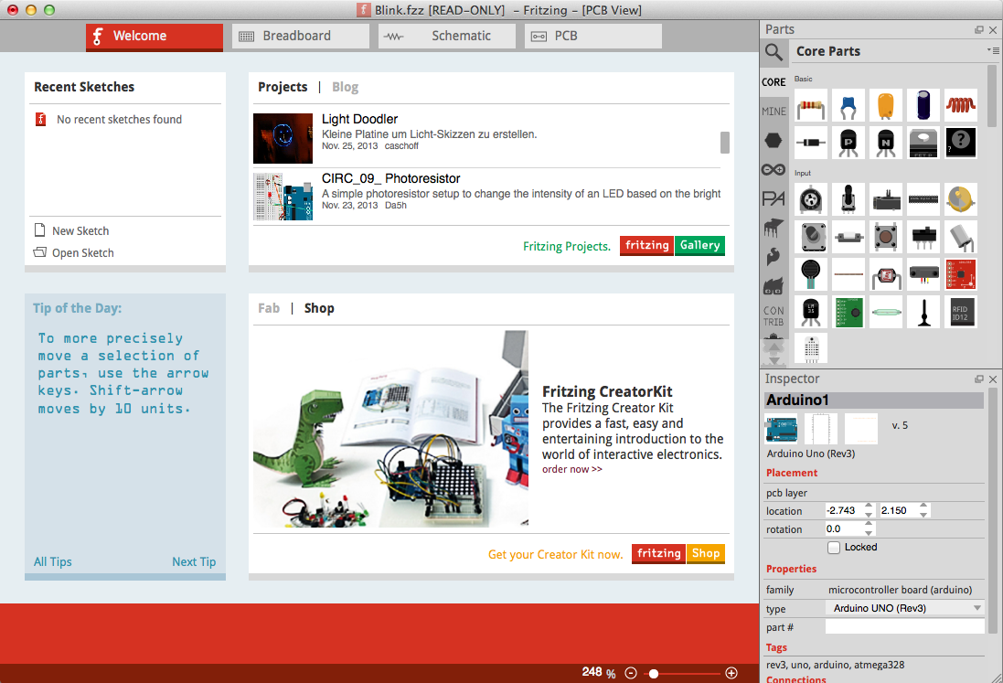
The application has several features and functions that simplify the process of designing a circuit, including the following convenient tools to help you design your circuits:
- The Part Library offers several components, both common and uncommon, created by the user community. You can also import a custom part into the library and use any of these parts in your circuit design.
- The Part Inspector allows you to configure parameters for each part as you add it to your design. If you add a resistor or capacitor, you can change the value of the resistor or the capacitor using the inspector. If you add an LED, you can change its color, and so on.
- The Part Creator is a feature that allows users to design their own components for their circuits, although the part library is comprehensive enough for most designs.