Circuit Assembly
To test if a circuit design works correctly you need to assemble it by connecting together all the required microcontrollers, modules, and electronic components.
With sophisticated design tools, you can test your designs using the software itself, thus not requiring to do any physical assembly. But when learning about building microcontroller solutions you will eitehr refer to existing designs or use a relatively simple circuit design tool like Fritzing. In which case to test your design you will need to assemble the circuit. Fortunately Breadboards offer a very simple solution for assembling circuits.
Breadboards
A breadboard is a base that can be used to assemble electronic circuits. All electronic components are designed to have pins. The breadboard has a series of holes, which are internally connected in a specific pattern. To add a component to the circuit, you have to push the pins of the components into the appropriate holes in the breadboard to make the right connections with other ones. Insulated wires, known as jumper wires, can also be used to connect one component to another. The components and wires can be moved around easily to change the circuit on demand. Pushing a component into the breadboard needs only light pressure, and the component fits snugly enough to stay in place even if the board is turned upside down but can be removed with a light pull.
The biggest advantage of breadboards is that they allow solderless connections. Soldering is a method where electronic components and wires are connected by melting a specific type of metal called solder, which you often find printed on circuit boards. Soldering is not easy as it involves a high-temperature soldering iron, and the connections made are permanent, making them difficult to change.
The disadvantage of breadboards is that the components and jumper wires come out very easily and therefore breadboards can only be used for learning and prototyping not for assemblies that need to be used for a long time.
Breadboard Layouts
Breadboards are rectangular in shape and typically come in three sizes, so you can choose a board that ia appropriate for your circuit and the number of components. Looking at a full-size board laid horizontally (shown below), you can see that they have a series of holes laid out in rows and columns.
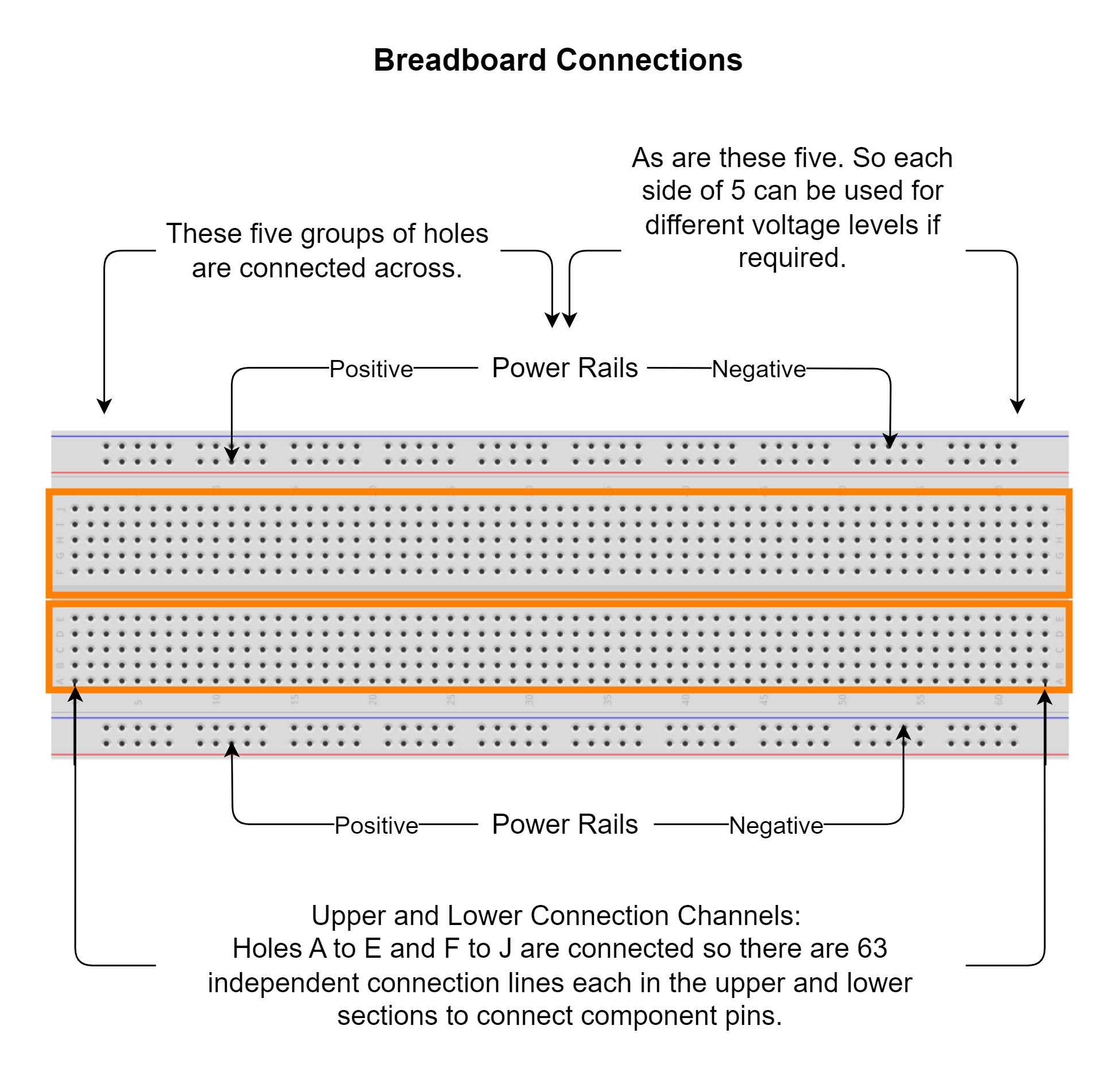
The first two rows from the top and the last two rows from the bottom are known as power rails or buses. They are typically used to supply electrical power to your circuit, especially when you connect them to a battery pack or other external power supply. They are generally not to be used to connect components. Each power rail row has 10 sets of 5 holes that make a total of 50 holes in every row. These are not lettered or numbered. Some breadboards have the buses broken in half along the length of the breadboard (useful if you need to supply your circuit with two different voltage levels).
Generally, a circuit requires one voltage level. You can connect the left and right and top and bottom connected sets, one for positive and one for negative, so that any of the holes on the rails can be used as the positive or negative connection. Such an arrangement gives you more flexibility to lay out your components. If your circuit needs two voltage levels you can use one half each for a level.
The rows in between the power rails are used to connect components. The rows are lettered with A to E and F to J dividing the 10 rows into the upper and lower halves of 5 rows each. The columns are numbered from 1 to 63. Each hole can be referenced as a combination of a number and a letter; thus, the first hole will be 1A, and the last hole will be 63J.
In the component area, the 5 holes in the column in the upper half are connected to each other and similarly in the bottom half. But each column is not connected to the next column. So, holes 1A through 1E are connected and 1F through 1J, and so on across all columns through 63.
Connections
The connections between the holes are extremely important to understand as an error in connection could cause your circuit to fail and in severe cases, may damage some components.
See the image below for the correct and incorrect ways to connect components onto the breadboard.
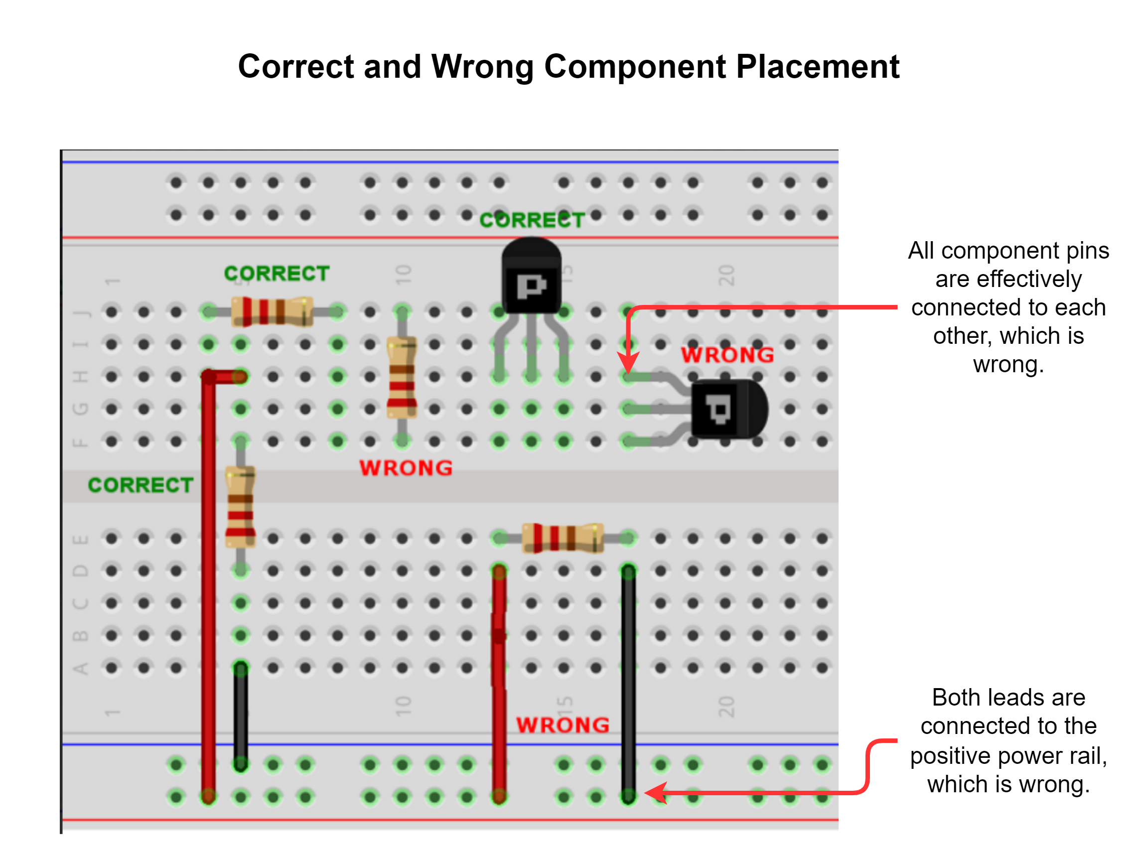
While the general approach with all breadboards is as explained above, the exact layouts may vary. Before starting your circuit assembly, understand the layout of your breadboard if it is labeled differently or has no labeling at all.
Jumper Wires
Jumper wires are used to make connections on a breadboard. They are flexible but have stiff ends that are easy to push into the breadboard holes. In circuits with very few components, the leads can be connected directly, but once the number of components starts to increase, jumper wires are needed to make the connections. Jumper wires are also needed to connect the breadboard to the Arduino if required a direct power supply to the breadboard. These wires usually come in varying colors (metal on the inside with colored plastic insulation on the outside) to allow you to color-code your circuit.
Color-Coding Circuits
Using differently-colored connecting wires will not change how your circuit works but color coding your wires can help you stay organized. For power connections, a red wire is conventionally used to connect to the positive connection of the power source, while black is the negative connection and ground. Some circuit components and some sensors come with colored wires already attached to them. In such cases, keeping track of these colors does matter.