Rain Sensor
Rain sensors detect rainfall and can trigger automatic actions like activating windshield wipers or closing windows. They typically work by measuring changes in electrical conductivity, light reflection, or other properties caused by water droplets on a sensor surface.
Two common types of rain sensors are:
-
Conductivity-based Rain Sensors: These sensors have a sensing pad with exposed conductive traces. When raindrops fall on the pad, they create a conductive bridge between the traces, lowering the resistance. This change in resistance is detected, and the sensor outputs a signal indicating the presence and sometimes the intensity of rain.
-
Optical Rain Sensors: These sensors, often found in cars, use infrared light and a photodiode to detect water on the windshield. An infrared beam is directed at the windshield, and the amount of light reflected back to the sensor is measured. When it rains, the water scatters the light, reducing the amount reflected back, which triggers the sensor.
A rain sensor usually comprises a sensing pad on which rainfall is detected and a circuit that processes the signal from the sensing pad and generate a digital or analog signal indicating the presence and/or intensity of rain.
Sensors such as the rain sensor often come with a pad or a probe that is exposed to the elements being measured (such as water) and a module circuit. The pad or probe generates a varying voltage which is sent to the module circuit. The module circuit interprets the value and further outputs the analog value and also a digital signal if you only want to have a binary status of whether or not the element was detected. The threshold is set by a potentiometer on the circuit module. When setiing it up for you project you have to adjust the potentiometer to the threshold you would like for it to send a HIGH digital ouput.
Components
| Component | Purpose |
|---|---|
| Arduino Nano | The microcontroller |
| Rain sensor Pad | The rain sensor pad |
| Rain Sensor Module | The rain sensor module |
Circuit Diagram
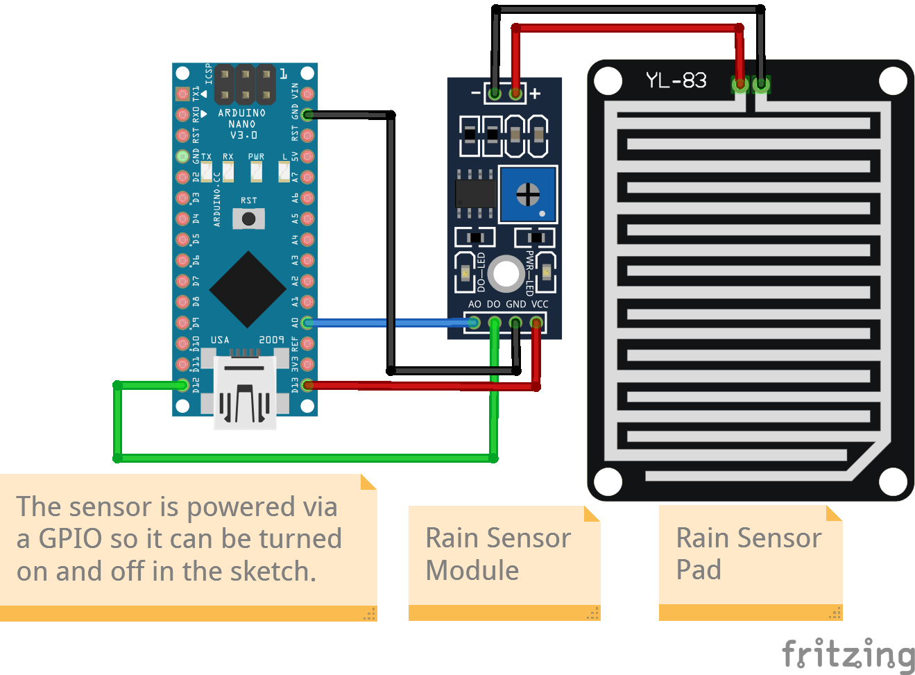
Connections
The rain sensor pad has two output pins (generally marked +ve and -ve). Connect these pins to the corresponding inputs pins (also marked +ve and -ve) on the rain sensor module.
Rain Sensor Module
Powering the sensor programmatically
We are going to do something different here with the power to the sensor. Normally we would connect the sensor power pin to the power supply pin of the board so that it will remain powered on as long as the board is powered on. This time we will connect the sensor power pin to one of the board GPIOs. The sensor can then be turned on or off in the sketch by sending a HIGH or a LOW signal to that pin.
| Nano Pin | Rain Sensor Module Pin |
|---|---|
| A0 | AO |
| D12 | DO |
| D13 | VCC (see note above) |
| GND | GND |
Code
/*
  Project: Physical Computing
  Circuit: Rain Sensor
  Boards Supported: UNO R3/R4, Nano, ESP32
  Function: This project read the value from a rain sensor.

  Author: STEMVentor Educonsulting

  This code is copyrighted. Please do not reuse or share for any purpose other than for learning with subscribed STEMVentor programs. This code is for educational purposes only and is not for production use.
*/

// LIBRARIES

// PIN DEFINITIONS
#define RAIN_SENSOR_DIGITAL_PIN 12
#define RAIN_SENSOR_ANALOG_PIN A0
// We will be programmatically turning the sensor on and off with this pin.
#define RAIN_SENSOR_POWER_PIN 13

// GLOBAL CONSTANTS

// GLOBAL VARIABLES

// INITIALIZE OBJECTS

// LOCAL FUNCTIONS

// Read Rain sensor values.
void readRainSensorValues()
{
  digitalWrite(RAIN_SENSOR_POWER_PIN, HIGH); // Turn the sensor ON
  delay(300); // Allow power to settle
  uint8_t is_raining = digitalRead(RAIN_SENSOR_DIGITAL_PIN); // Read the sensor output
  digitalWrite(RAIN_SENSOR_POWER_PIN, LOW); // Turn the sensor OFF

  // Print whether it's raining or not and how heavily.
  // Note that the analog signal from the sensor pad is compared
  // to a threshold (reference voltage) set by a potentiometer on the module.
  // If the amount of water on the sensing pad is below the set threshold,
  // the comparator gives a HIGH digital output signal at the digital pin (DO)
  // else gives a LOW signal.

  if(is_raining == LOW){
    Serial.println("It's raining!");

    // And read and print the intensity from the analog signal.
    uint8_t rain_intensity = analogRead(RAIN_SENSOR_ANALOG_PIN);
    Serial.print(map(rain_intensity, 0, 1023, 0, 100));
    Serial.println("% intensity");
  }else{
    Serial.println("It's not raining!");
    // No need to read or print the intensity.
  }

}

// THE setup FUNCTION RUNS ONCE WHEN YOU PRESS RESET OR POWER THE BOARD.
void setup() {
  Serial.begin(9600);

  pinMode(RAIN_SENSOR_DIGITAL_PIN, INPUT);

  pinMode(RAIN_SENSOR_POWER_PIN, OUTPUT);
  // Make sure the sensor starts turned off.
  digitalWrite(RAIN_SENSOR_POWER_PIN, LOW);

  Serial.println("The Rain sensor is ready!");
}

// THE loop FUNCTION RUNS OVER AND OVER AGAIN FOREVER UNTIL THE BOARD IS POWERED OFF.
void loop() {
  readRainSensorValues();
  delay(10000*10); // In milliseconds
}