RGB LED
There are two types of LEDs: single-color LEDs and RGB LEDs. While single-color LEDs can emit any one color, RGB LEDs can emit multiple colors. RGB LEDs have a wide range of applications such as decorative lighting and in circuits where visual feedback through different colors is needed.
Single-color LEDs have two leads, positive (anode) and negative (cathode).
RGB LEDs have fours leads. They can be setup to have a common cathode or a common anode. In the common cathode setup, there are one negative and three positive leads, one for each of the primary colors (Red, Green, and Blue). In the common anode setup, there are one positive and three negative leads (one for each of the primary colors). By varying the power of the signal supplied to the RGB leads multiple colors can be emitted.
You can learn how to connect and control a single color LED in the Potentiometer project. Here we will cover the RGB LED.
The signal power can be varied physically by attaching a Potentiometer to each of the RGB leads or programatically by sending PWM signals to the RGB leads. We will look at both approaches in this project.
Components
| Component | Purpose |
|---|---|
| Arduino Nano | The microcontroller. |
| Potentiometer | To send a varying voltage to the RGB LED. Three required, one for each color. |
| RGB LED | A common cathode RDB LED controlled by the potentiometers. |
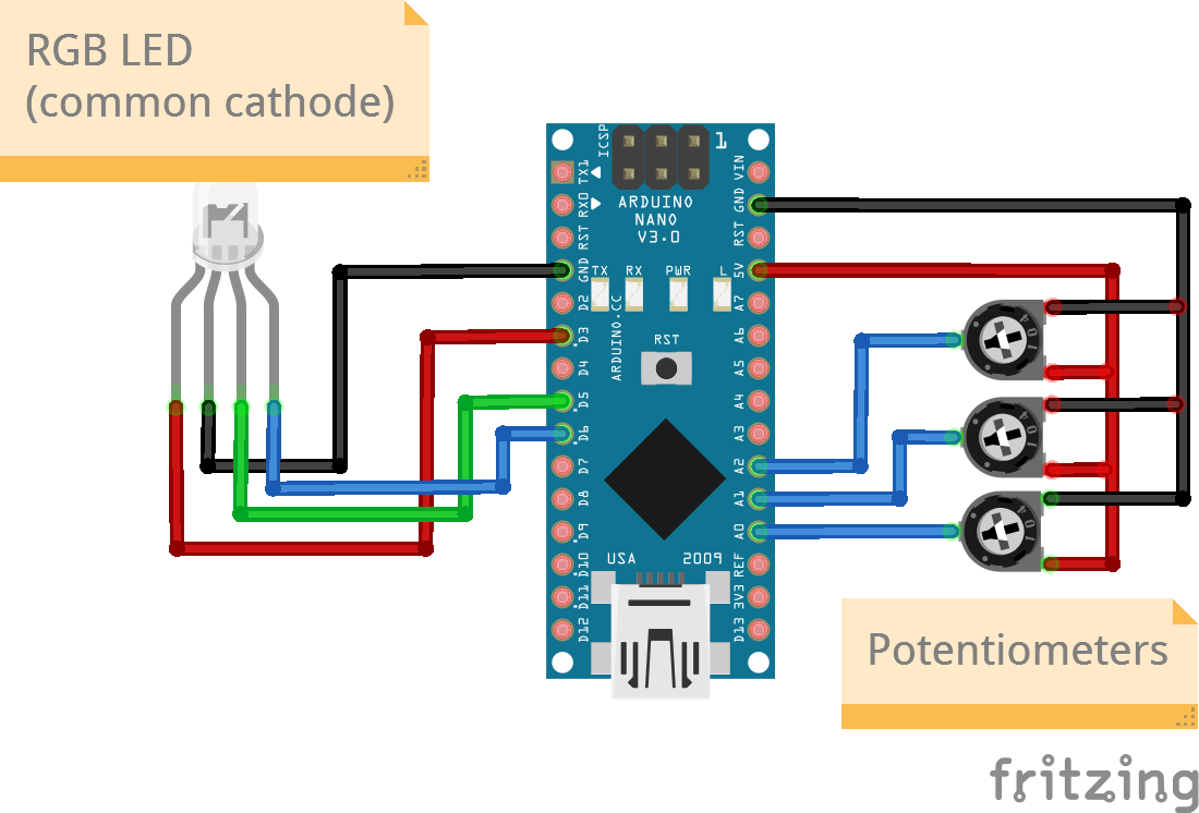
Circuit Diagram
Connections
RGB LED Connections (Common Cathode)
| Nano Pin | RGB LED Pin |
|---|---|
| D3(PWM) | Red Anode |
| D5(PWM) | Green Anode |
| D6(PWM) | Blue Anode |
| 5V | VCC |
| GND | GND |
Potentiometer Connections
Three pots will be required, one for each color.
| Nano Pin | Pot Pin |
|---|---|
| A0 | Signal (Pot 1) |
| A1 | Signal (Pot 2) |
| A2 | Signal (Pot 3) |
| 5V | VCC (all pots) |
| GND | GND (all pots) |
Code
/*
  Project: RGB LED with Potentiometers
  Circuit: RGB LED - Potentiometer
  Boards Supported: UNO R3/R4, Nano, ESP32

  Description: This project shows you how to light up an RGB LED with multiple colors using three potentiometers.

  Author: STEMVentor Educonsulting

  This code is copyrighted. Please do not reuse or share for any purpose other than for learning with subscribed STEMVentor programs. This code is for educational purposes only and is not for production use.
*/

// LIBRARIES

// PIN DEFINTIONS
#define RGBLED_RED_PIN = 3
#define RGBLED_GREEN_PIN = 5
#define RGBLED_BLUE_PIN = 6

int RED_POT_PIN = A0
int GREEN_POT_PIN = A1
int BLUE_POT_PIN = A2

// CONSTANT DEFINITIONS

// LOCAL FUNCTIONS
void setup() {
  pinMode(RGBLED_RED_PIN, OUTPUT);
  pinMode(RGBLED_BLUE_PIN, OUTPUT);
  pinMode(RGBLED_GREEN_PIN, OUTPUT);

  // To test the RGB LED cycle through the three colors
  // by setting color values programmatically.
  // FOR COMMON ANODE
  // RED
  analogWrite(RGBLED_RED_PIN, 255);
  analogWrite(RGBLED_GREEN_PIN, 0);
  analogWrite(RGBLED_BLUE_PIN, 0);
  delay(2000);
  // GREEN
  analogWrite(RGBLED_RED_PIN, 0);
  analogWrite(RGBLED_GREEN_PIN, 255);
  analogWrite(RGBLED_BLUE_PIN, 0);
  delay(2000);
  // BLUE
  analogWrite(RGBLED_RED_PIN, 0);
  analogWrite(RGBLED_GREEN_PIN, 0);
  analogWrite(RGBLED_BLUE_PIN, 255);
  delay(2000);

  // FOR COMMON CATHODE
  // RED
  // analogWrite(RGBLED_RED_PIN, 0);
  // analogWrite(RGBLED_GREEN_PIN, 255);
  // analogWrite(RGBLED_BLUE_PIN, 255);
  // delay(2000);
  // // GREEN
  // analogWrite(RGBLED_RED_PIN, 255);
  // analogWrite(RGBLED_GREEN_PIN, 0);
  // analogWrite(RGBLED_BLUE_PIN, 255);
  // delay(2000);
  // // BLUE
  // analogWrite(RGBLED_RED_PIN, 255);
  // analogWrite(RGBLED_GREEN_PIN, 255);
  // analogWrite(RGBLED_BLUE_PIN, 0);
  // delay(2000);
}

void controlRGBLED(){
  // Reads the potentiometer value which will be between 0 and 1023 for a Nano
  // converts it to a value between 0 and 255
  // and writes the value to the RGB LED pin (R, G, or B) corresponding to the pot.

  uint8_t red_pot_value = analogRead(RED_POT_PIN);
  // Scale the value to between 0 and 255 for the PWM pin.
  // RGB LEDs come with two pin types: Commmon Anode and Common Cathode.
  // Scale the value depending on the type.
  // FOR COMMON ANODE
  uint8_t red_pin_value = map(red_pot_value, 0, 1023, 0, 255);
  // FOR COMMON CATHODE
  // uint8_t red_pin_value = map(red_pot_value, 0, 1023, 255, 0);
  analogWrite(RGBLED_RED_PIN, red_pin_value);

  uint8_t green_pot_value = analogRead(GREEN_POT_PIN);
  // FOR COMMON ANODE
  uint8_t green_pin_value = map(green_pot_value, 0, 1023, 0, 255);
  // FOR COMMON CATHODE
  // uint8_t green_pin_value = map(green_pot_value, 0, 1023, 255, 0);
  analogWrite(RGBLED_GREEN_PIN, green_pin_value);

  uint8_t blue_pot_value = analogRead(BLUE_POT_PIN);
  // FOR COMMON ANODE
  uint8_t blue_pin_value = map(blue_pot_value, 0, 1023, 0, 255);
  // FOR COMMON CATHODE
  // uint8_t blue_pin_value = map(blue_pot_value, 0, 1023, 255, 0);
  analogWrite(RGBLED_BLUE_PIN, blue_pin_value);
}

void loop() {
  controlRGBLED();
  delay(1000);
}