Joystick
A joystick is an input device that is used for providing directional inputs to a microcontroller board generally used to control moving objects, physical or on-screen, by translating the directional inputs to movement.
A joystick can be pushed in any direction along a circle, the most typical directions being up (north), down (south), left (west), right (east), and diagonal (northwest, northeast, southwest, and southeast). Joysticks may also provide an additional push or click input when the stick is pressed down.
The joystick input is translated into movement depending on the context and the object being moved.
For example, if a joystick is controlling a car, the up and down movements will translate to forward and backward movements for the car, the left and right movements will turn the car left or right. And any diagonal movements may control the degree of turn.
If the joystick is controlling a flying airplane, the up and down movements will translate to nose down and nose up movements for the airplane (known as the pitch), the left and right movements, will cause the airplane to tip its wings left or right (known as the roll) and at the same time turn left or right (known as the yaw).
The joystick module has two analog ouput pins that output analog signals, one for the up-down (y-axis) movement, and one for the left-right (x-axis) movement. On the y-axis pin the signal voltage will go from 0 when the joystick is moved to the extreme bottom and the maximum operating voltage of the module (5V or 3.3V) when the joystick is moved to the extreme top (or it could be the other way round depending on how the joystick is calibrated). The voltage will vary similarly for the x-axiz movement from extreme left to extreme right. When the joystick is in its center (known as resting) position, the output voltage is about half of the operating voltage.
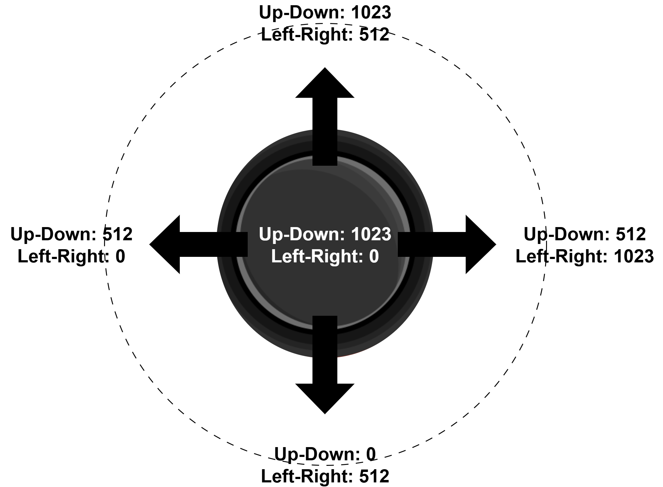
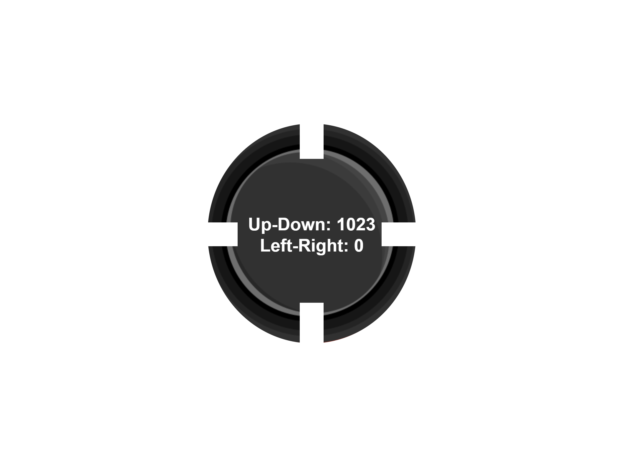
The analog values are read by the microcontroller’s Analog-to-Digital Converter (ADC) and converted to a value between 0 and 1023. The microcontroller program can translate these values into motion as required.
If the joystick has a push or click signal pin, it will send a digital (HIGH or LOW) signal to the microcontroller.
This project reads values from a Joystick and displays the readings on the serial monitor.
Components
| Component | Purpose |
|---|---|
| Arduino Nano | The microcontroller |
| Dual axis joystick | Joystick for input |
Circuit Diagram
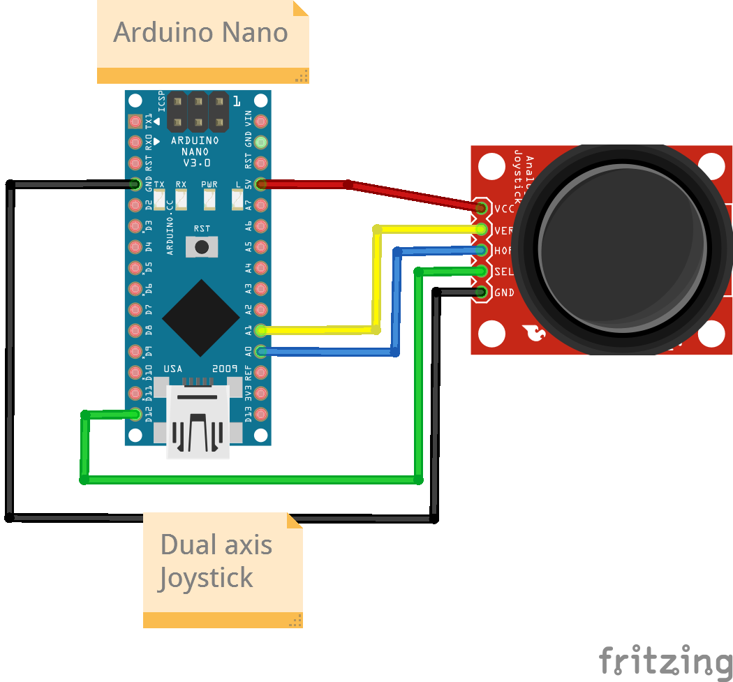
Connections
Dual-axis Joystick Pin Connections
| Nano Pin | Joystick Pin |
|---|---|
| A0 | Vertical Pin |
| A1 | Horizontal Pin |
| D12 | Select Pin |
| 5V | VCC |
| Gnd | Gnd |
Code
/*
  Project: Process Joystick Input
  Project Description: This sketch reads the joystick input, translates it to a direction, and prints the input value and direction on the serial monitor.

  Author: STEMVentor Educonsulting

  This code is copyrighted. Please do not reuse or share for any purpose other than for learning with subscribed STEMVentor programs. This code is for educational purposes only and is not for production use.
*/

// LIBRARIES

// PIN DEFINITIONS

// For Arduino Nano
#define VERTICAL_PIN A1
#define HORIZONTAL_PIN A0
#define SELECT_PIN  12

// For ESP32
// #define VERTICAL_PIN 12
// #define HORIZONTAL_PIN 13
// #define SELECT_PIN  14

// GLOBAL VARIABLES
// The range of analog values for a Nano is 0-1024 while for an ESP32 it is 0-4096.

// Set thresholds to count as a complete movement in a direction.
// This code assumes the joystick module sends a value of 0 for extreme down and left
// and a value of 1023 for extreme up and right.
// For Arduino Nano
const int north_threshold = 1000; // Greater than
const int south_threshold = 100; // Less than
const int west_threshold =  100; // Less than
const int east_threshold = 1000; // Greater than

/* INITIALIZE OBJECTS */

/* LOCAL FUNCTIONS */

// Read joystick values
void readJoystickValues()
{
  int vertical_value = analogRead(VERTICAL_PIN); // Read the vertical pin value
  int horizontal_value = analogRead(HORIZONTAL_PIN); // Read the horizontal pin value
  bool select_value = digitalRead(SELECT_PIN) ; // Read the sel pin value

  // Serial print the values
  Serial.println(vertical_value);
  Serial.println(horizontal_value);
  Serial.println(select_value);

  // Position identification logic customized as required by your application.
  Serial.println("Select pressed!");

  if(vertical_value > north_threshold){
    if(horizontal_value < west_threshold){
      Serial.println("Pushed North-West!");
    }else if(horizontal_value > east_threshold){
      Serial.println("Pushed North-East!");
    }else{
      Serial.println("Pushed North!");
    }
  }else if(vertical_value < south_threshold){
    if(horizontal_value < west_threshold){
      Serial.println("Pushed South-West!");
    }else if(horizontal_value > east_threshold){
      Serial.println("Pushed South-East!");
    }else{
      Serial.println("Pushed South!");
    }
  }else{ // Vertical value is neither north or south, so centered.
    if (horizontal_value < west_threshold){
      Serial.println("Pushed West!");
    }else if (horizontal_value > east_threshold){
      Serial.println("Pushed East!");
    }else{
      Serial.println("Joystick centered!");
    }
  }
}

void joystickSetup()
{
  // Joystick pins
  pinMode(VERTICAL_PIN, INPUT);
  pinMode(HORIZONTAL_PIN, INPUT);
  // for ESP32
  // pinMode(SELECT_PIN, INPUT_PULLUP);
  // for Arduino Nano
  pinMode(SELECT_PIN, INPUT);
}

/* SETUP CODE: runs once when the board starts up or resets */
void setup() {
  // Start the serial communication with baud rate suitable for your components.
  Serial.begin(9600);
  joystickSetup();
  Serial.println("The joystick is ready!");
}

/* MAIN LOOP: runs repeatedly at a very high frequency (1000s of times a second) */
void loop() {
  delay(3*1000);
  readJoystickValues();
}