Universal Asynchronous Receiver-Transmitter
An UART is a peripheral device for asynchronous serial communication that allows two devices to exchange serial data. An UART is usually a part of an integrated circuit (IC) used in computers, microcontrollers, and embedded systems for device-to-device communication.
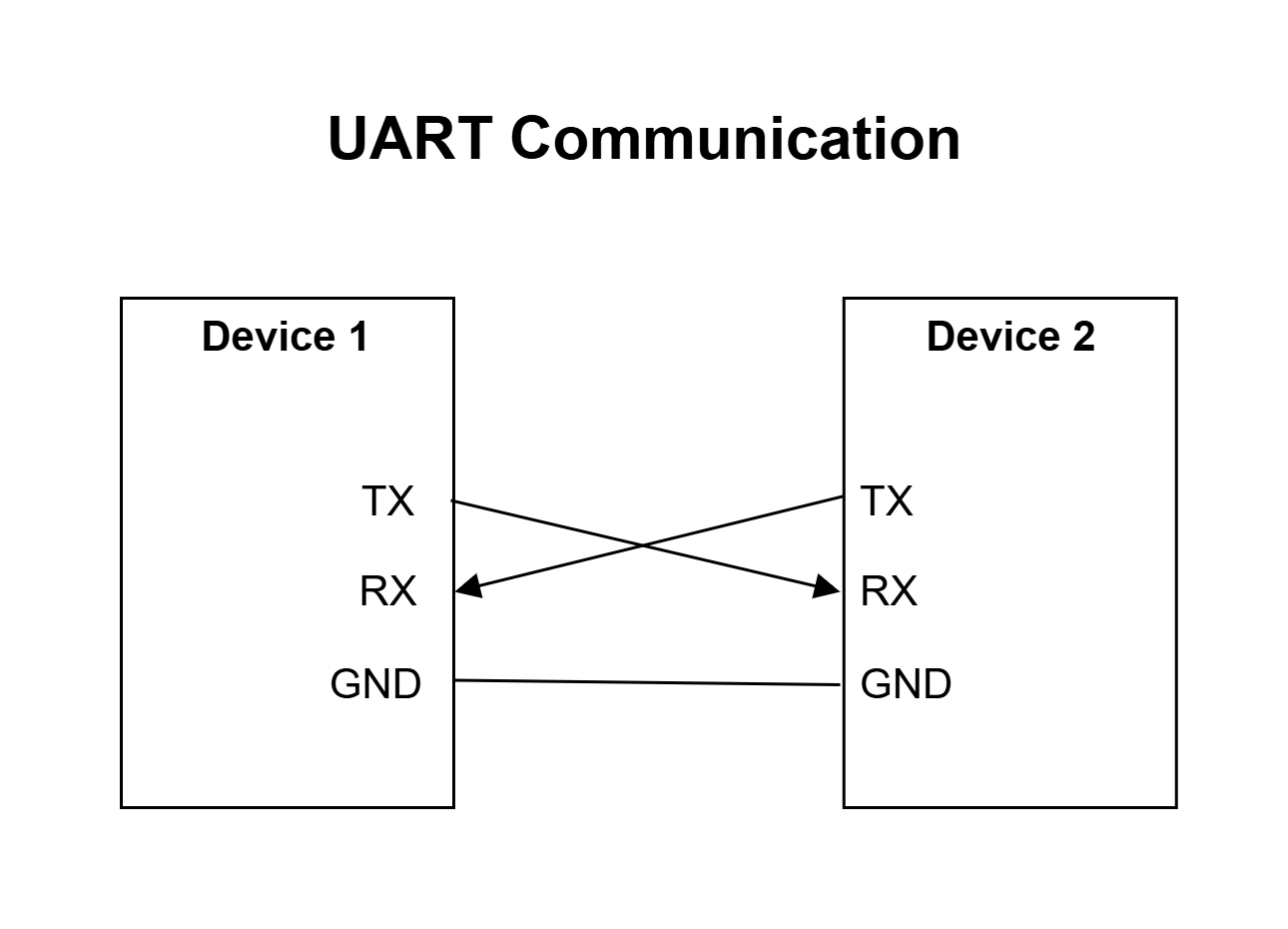
The UART circuit has only two connectors, one to send or transmit data (the TX connector) and one to receive data (the RX connector). The sending and receiving devices both need to have a UART component. The TX connector on one UART is connected to the RX connector on the other UART and vice versa.
It can communicate in simplex (data can be transmitted in one direction only), half-duplex (data can be transmitted on both directions but only one at a time), or full-duplex modes (data can be transmitted in both directions at the same time).
The sending UART converts parallel data from the device it is connected to into serial form, transmits it in serial to the receiving UART, which converts the serial data back into parallel data for the receiving device.
UARTs transmit data asynchronously, which means there is no clock signal to synchronize the output of bits from the transmitting UART to the sampling of bits by the receiving UART. Both sides are set to a pre-configured baud rate that dictates the speed and timing of data transmission. In addition, the transmitting UART adds start and stop bits to the data packet. These bits define the beginning and end of the data packet, so the receiving UART knows when to start reading the bits.
When the receiving UART detects a start bit then starts to read the incoming bits at a specific frequency known as the baud rate. Baud rate is a measure of the data transfer speed, expressed in bits per second (bps). Both UARTs must operate at the same baud rate and be configured to transmit and receive the same data packet structure.
UART is the communication protocol that is used to exchange data between a computer and the microcontroller (in our projects the Arduino, ESP32 and Raspberry Pico boards) when uploading a program to the microcontroller or when reading data from a microcontroller.
UART Data Exchange
While there are multiple communication protocols between boards and components, one of the simplest is UART (or Serial) Communication which requires a wired connection between the boards.
In this solution the ESP32, Nano Circuit 2 and the Pico Circuit will exchange data with each other over UART. The Nano 1 and the Pico will display the received data on the LCD, while the ESP32 will display the received data on the OLED.
The circuit diagram below shows the UART connections between the boards.
The Nano Circuit 1 will use LoRa to exchange data with the ESP32 and so is not included here.
UART Pins
Each board generally has at least one set (TX and RX) of hardware UART pins. However, if the board is connected to the computer for uploading code or exchanging data with the Serial Monitor, one set of hardware UART pins is blocked.
As an alternative (or in addition) to the hardware UART pins you can define any two GPIO pins as TX and RX pins in the microcontroller program.
The ESP32 has two sets of hardware UART pins. While one is blocked for communication with the computer if connected, the other set if available for general use.
Circuit Diagram
The Green (TX) and Blue (RX) wires between the Nano 1, Pico, and ESP32 are the UART connections. The Nano 2 is not connected to any board for UART, it will be connected to the ESP32 over LoRa later.

ESP32 Circuit Connections
Board pin numbers are those printed on the board while code pin numbers need to be used in code (generally indicated in the pinout diagram as the GPIO pin number). They may be the same or different, depending on the board.
Board Pin | Code Pin | Mode | Component | Pin |
|---|---|---|---|---|
| D13 | 13 | Hardware UART1 TX | Nano 2 | A1 (RX) |
| D14 | 14 | Hardware UART1 RX | Nano 2 | A2 (TX) |
| RX2 | 16 | Hardware UART2 RX | Pico | D4 (TX) |
| TX2 | 17 | Hardware UART2 TX | Pico | D7 (RX) |
Nano Sensor and Controller Circuit Connections
Board Pin | Code Pin | Pin Mode | Component | Pin |
|---|---|---|---|---|
| A1 | A1 | Software UART RX | ESP32 | 13 (TX1) |
| A2 | A2 | Software UART TX | ESP32 | 14 (RX1) |
Pico Sensor and Controller Circuit Connections
Board Pin | Code Pin | Mode | Component | Pin |
|---|---|---|---|---|
| 11 | 8 | Software UART TX | ESP32 | 16 (RX2) |
| 12 | 9 | Software UART RX | ESP 32 | 17 (TX2) |
Code
The code for this circuit is distributed across multiple files, so will not be displayed here. It will be available for download for subscribers.