Switch
This project demonstrates how to read the state of a switch which can then be used to take some action (such as switch on an LED or sound a buzzer). In this project we will use the on-board LED available on all boards.
There are two types of switches:
- On/Off Switch: The switch has two positions on and off and remains in either position unless manually moved to the other position.
- Pushbutton Switch: The pushbutton switch normally stays in the off position, turns on when pressed, turns off when released, and stays off until pressed again.
The connections and sketch for both types of switches are the same, only the physical action to turn the on and off differs.
Read about Disconnected Pins and Pull-up Resistors before programming for a switch.
Components
| Component | Purpose |
|---|---|
| Arduino Nano | The microcontroller. |
| 4-pin Switch | The on/off switch. |
| On-board LED | The LED to switch on and off |
Circuit Diagram
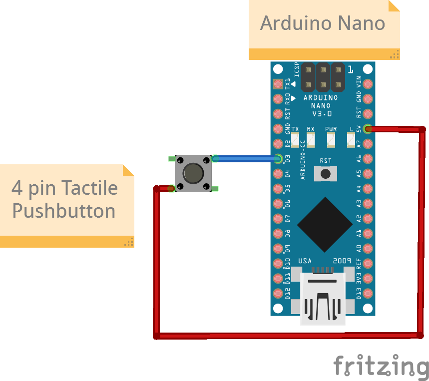
Connections
4-pin Switch
On a 4-pin switch Pin1 and Pin2 are any two pins out of the 4 that are diagonal to each other.
| Arduino Nano Pin | Switch Pin |
|---|---|
| D3 | Pin1 |
| 5V | Pin2 |
Code
switch.ino
/*
  Project: Physical Computing.
  Function: Reads the state of a switch.
  Circuit: Switch.
  Boards Supported: UNO R3/R4, Nano, ESP32.

  Description: Function description.

  Author: STEMVentor Educonsulting

  This code is copyrighted. Please do not reuse or share for any purpose other than for learning with subscribed STEMVentor programs. This code is for educational purposes only and is not for production use.
*/

// LIBRARIES

// PIN DEFINTIONS
#define SWITCH_PIN 3

// CONSTANT DEFINITIONS

// GLOBAL VARIABLES
uint8_t switch_state = LOW;  // To read the switch state.

// INITIALIZE OBJECTS

// LOCAL FUNCTIONS
void buttonSetup()
{
  // Set the pin mode for the switch pin as an input with the internal pull-up resistor.
  pinMode(SWITCH_PIN, INPUT_PULLUP);
}

void LEDSetup(){
  // Set the pin mode for the on-board LED pin as output.
  pinMode(LED_BUILTIN, OUTPUT);
  digitalWrite(LED_BUILTIN, LOW);
}

// Read the button state and turn the LED on or off.
void readButtonState()
{
  // Read the value of the pushbutton state.
  button_state = digitalRead(PUSHBUTTON_PIN);
  Serial.print("Switch state: ");
  // Note the reverse logic (HIGH = OFF) since a pull-up resistor is being used.
  if(button_state == HIGH){
    Serial.println("OFF");
    digitalWrite(LED_BUILTIN, LOW);
  } else {
    Serial.println("ON");
    digitalWrite(LED_BUILTIN, HIGH);
  }
}

// THE setup FUNCTION RUNS ONCE WHEN YOU PRESS RESET OR POWER THE BOARD.
void setup() {
  Serial.begin(9600);
  buttonSetup();
  Serial.println("The board is ready. Running sketch to read switch state.");
}

// THE loop FUNCTION RUNS OVER AND OVER AGAIN FOREVER UNTIL THE BOARD IS POWERED OFF.
void loop() {
  readButtonState();
  delay(1000); // Read state every second.
}