Connections
Circuit Diagram
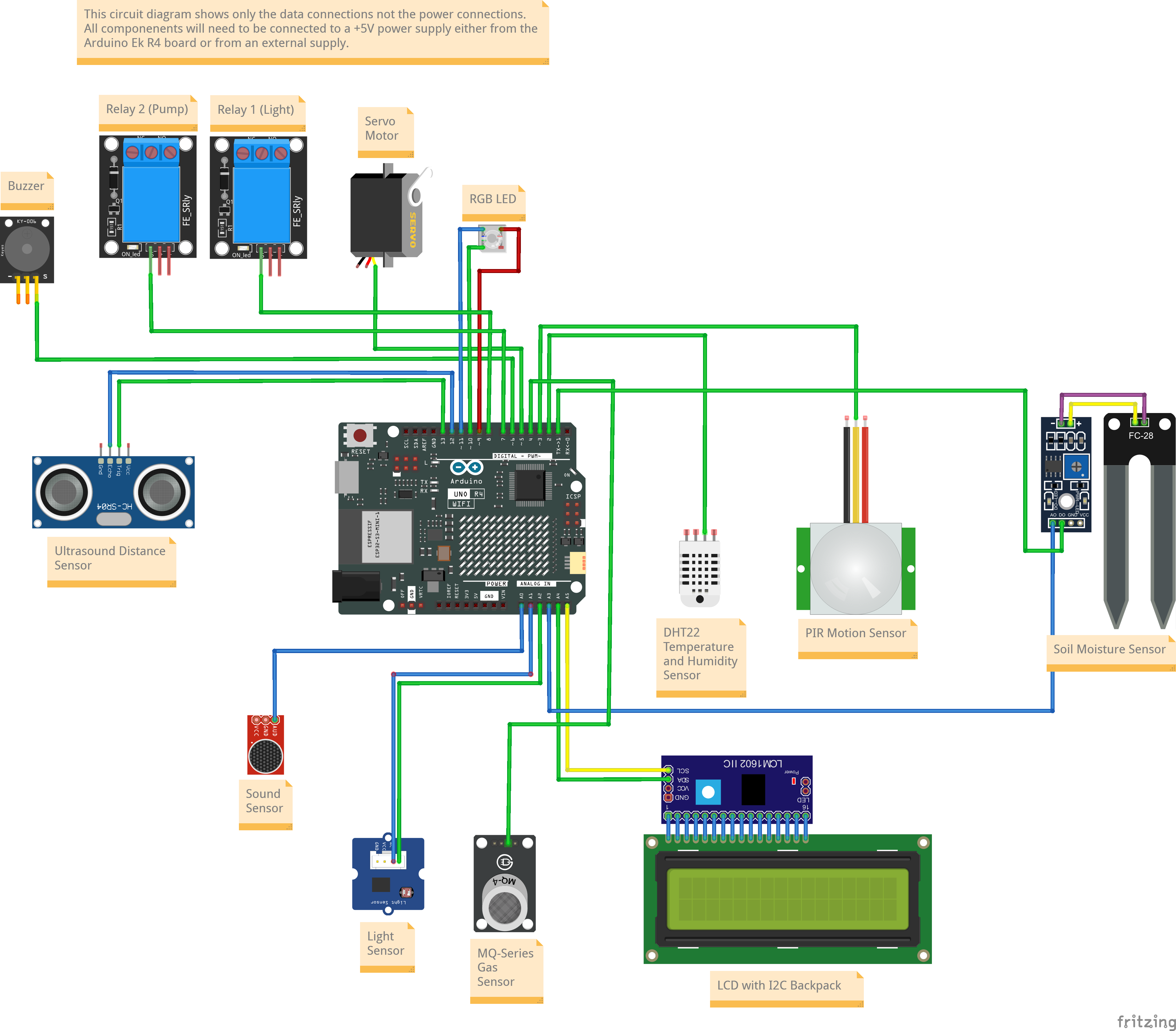
Connections
Board pin numbers are those printed on the board while code pin numbers need to be used in code (generally indicated in the pinout diagram as the GPIO pin number). They may be the same or different, depending on the board. Analog pins can also be referred to as their digital pin name equivalents.
The Ek R4 has separate I2C pins for SDA and SCL but these are internally connected to (so the same as) A4/D18 and A5/D19. If an I2C component is connected to either pair. make sure the other pair is not used.
| Board (Code) Pin | Function | Component | Pin |
|---|---|---|---|
| D0 (0) | UART RX / Digital Out | Soil moisture sensor LM393 (5V) Will need to be disconnected when uploading code. | VCC |
| D1 (1) | UART TX / Digital In | Soil moisture sensor LM393 (5V) Will need to be disconnected when uploading code. | Digital Out |
| D2 (2) | Digital In | Temperature and Humidity Sensor DHT22 (5V) | Digital Out |
| D3 (3) | Digital In (Interrupt) | PIR Motion Sensor HSR501 (5V) | Digital Out |
| D4 (4) | Digital In | Gas Sensor MQ-135 (5V) | Digital Out |
| D5 (5) | Digital Out (PWM) | Servo Motor (5V) | PWM Signal |
| D6 (6) | Digital Out (PWM) | Buzzer (5V) | Digital In |
| D7 (7) | Digital Out | Relay 1 - Light (5V) | Signal |
| D8 (8) | Digital Out | Relay 2 - Submersible Pump (5V) | Signal |
| D9 (9) | Digital Out (PWM) | Common Cathode RGB LED Module (5V) | Red Anode |
| D10 (10) | Digital Out (PWM)/ SPI CS | Common Cathode RGB LED Module (5V) | Green Anode |
| D11 (11) | Digital Out (PWM)/ SPI COPI | Common Cathode RGB LED Module (5V) | Blue Anode |
| D12 (12) | Digital In/ SPI CIPO | Ultrasonic Distance Sensor HCSR05 (5V) | Echo |
| D13 (13) | Digital Out/ SPI SCK | Ultrasonic Distance Sensor HCSR05 (5V) | Trigger |
| A0/D14 (A0/14) | Analog In | Sound Sensor (5V) | Analog Out |
| A1/D15 (A1/15) | Analog In | Ambient Light Sensor LM393 (5V) | Analog Out |
| A2/D16 (A2/16) | Digital In | Ambient Light Sensor LM393 (5V) | Digital Out |
| A3/D17 (A3/17) | Analog In | Soil moisture sensor LM393 (5V) | Analog Out |
| A4/D18 (A4/18) | I2C SDA | 20x4 LCD with I2C Backpack (5V) | SDA |
| A5/D19 (A5/19) | I2C SCL | 20x4 LCD with I2C Backpack (5V) | SCL |
⚠️
Note that there are two additional pins marked SDA and SCL which are internally connected to A4 and A5 respectively. Use one or the other pair NOT BOTH.