Pinouts
One of the main conveniences that microcontroller boards provide is easy-to-connect pins that make it easy to connect components, other boards, and power supplies. Most of the pins on the board connect to the pins on the microprocessor, while some may be used for board-specific functions. Without the convenience of board pins, you would need to connect components to the microprocessor using a process of soldering which is actually more professional but difficult for beginners or casual circuit builders.
A typical microcontroller board will have the following types of pins:
-
GPIO Pins: General Purpose Input Output (GPIO) pins are used for connecting and exchanging data or signals with other components and boards. GPIO pins only work with digital signals, with two voltage levels, HIGH (representing a logical 1) and LOW (representing a logical 0).
Within the GPIO pins there are pins that serve a dual function:
If you do not need these pins for their specific functions, you can use them for regular digital input/output, but otherwise keep them free for their specific functions. The pin function, and whether it will function as an input or output pin is set programmatically in the microcontroller code.
-
Serial Communication (RX and TX): Two pins are generally reserved for serial communication with the computer the board is connected to for uploading code and exchanging data. If you use these pins to connect a component the component has to be disconnected if code needs to be uploaded.
-
PWM Pins: Pulse Width Modulation is a technique that generates a simulated analog signal using digital values. The ~ prefix on the pin label indicates that the pin supports PWM.
-
Interrupt Supported Pins: Sensors or other input components can send what is referred to as an interrupt to the board to let it know it has some data to share. This is more efficient that the baord continuously checking with the sensor. The * suffix on the pin label indicates that the pin supports interrupts.
-
UART Pins: Two pins (RX and TX) are made available for Universal Asynchronous Receiver-Transmitter (UART) Communication. These are similar to the RX and TX pins used for data exchange with the computer but can be used for UART comunication with components or other boards.
-
SPI Pins: Four pins (COPI, CIPO, CS, and SCL) are made available for Serial Peripheral Interface (SPI) Communication.
-
I2C Pins: Two pins (SDA and SCL) are made available for Inter-Integrated Circuit (I2C) Communication.
-
-
Analog Input Pins: Analog input pins can receive any value of input voltage between 0 and the operating voltage, in contrast to digital input pins than can only receive two values, 0 or the operating voltage. Boards have an Analog to Digital Converter (ADC) connected to these pins which convert the analog input into integer values between 0 and 1023. Analog pins cannot output a signal. However, analog pins can be used as digital input/output pins.
-
Power Out Pins: One pin will be the positive power supply voltage (VCC) and another pin will be the ground (GND). Boards may have one VCC pin supplying either 5V or 3.3V, or two VCC pins, one supplying 5V and one 3.3V.These pins can be used to supply power to connected components.
Pinout Diagrams
A board makes available its microprocessor pins and may add some pins of its own for additional functionality. A pinout diagram indicates the purpose/function of each pin on the board. The pins on a board are labelled, generally using letters and numbers (such as D1, D2, and so on for digital pins, A1, A2, and so on for analog pins, and with specific labels for other functions).
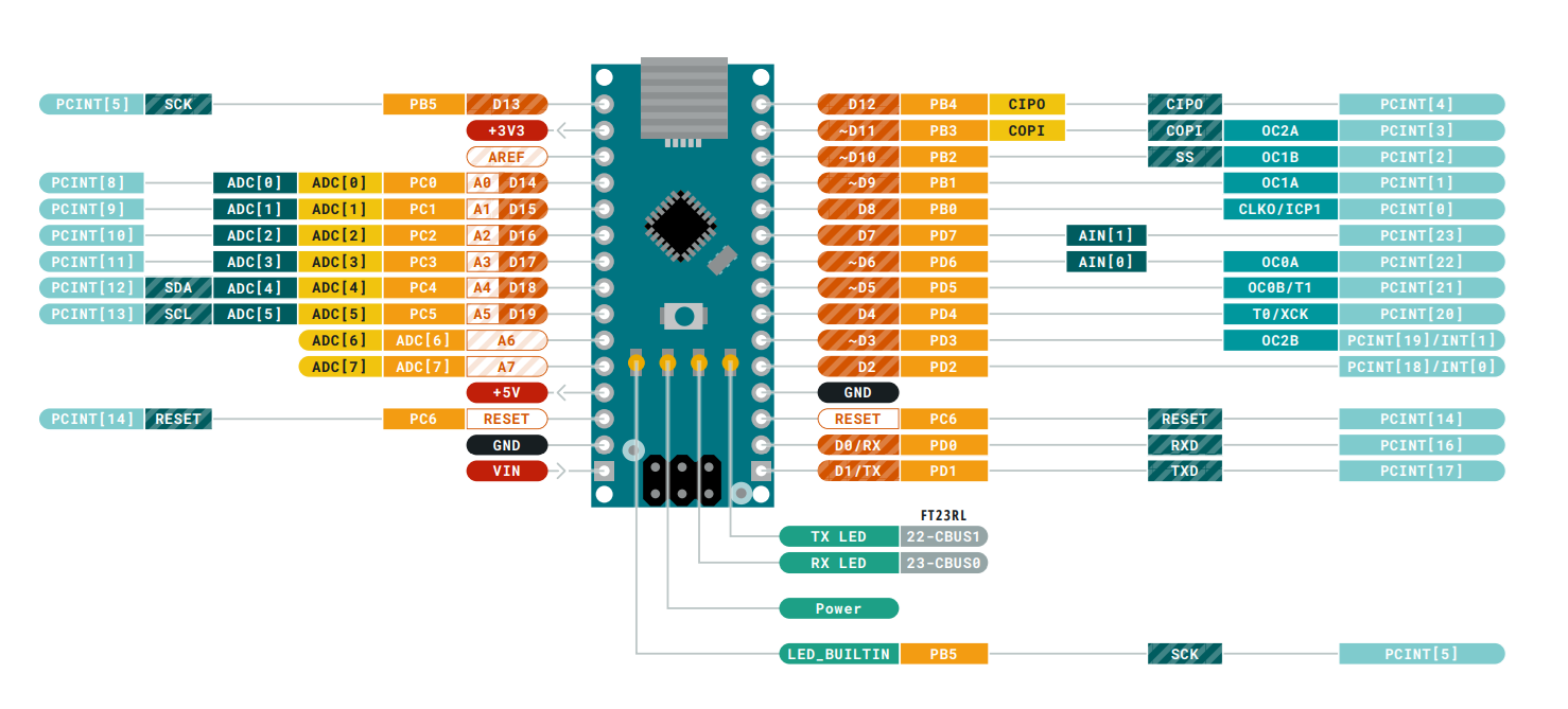
A pinout diagram provides a graphical view of the pins as laid out on a board. An example of a pinout diagram for an Arduino Nano is shown below.
General Guidance for using pins
The microprocessor also has pin numbers with specific functions which are used when the microprocessor is used without a board. When programming boards you have to use the board pin numbers, not the microprocessor pin numbers.
Some pins output a high or a low signal when the board boots up. Any active components connected to these boards will be affected. For example, an LED connected to a pin that outputs a high signal when booting up will light up.
Disconnected Pins
It is natural to assume that a pin that is not connected to anything is at 0V. In reality, a disconnected pin (also referred to as a floating pin) has an undefined state, as in it may actually have a voltage sufficient to indicate a HIGH signal or it may even randomly switch between having and not having any voltage. This is due to the electrical noise it can pick up from the electrical system in your house or other electric field sources.
This problem is notable when using a switch. If the switch is in the off position, the pin providing the voltage from the switch is expected to be at 0V and therefore provide a LOW signal, indicating that the switch is in the off position. With the possibility of a floating pin having a random voltage, it may continue to send a HIGH signal indicating that the switch is on when it is intended to be off.
Pull-up Resistors
While this concept is explained for your understanding, it is advisable not to actually use physical pull-up or pull-down resistors in your circuit. If the resistor values or connections are incorrect it could damage your microcontroller board or components.
Most microcontroller boards have what is known as an internal pull-up resistor that can be activated for a pin if required using code. Note that there is no INPUT_PULLLDOWN option since that is not recommended.
pinMode(3, INPUT_PULLUP)
To resolve this problem of the unknown state of a floating pin, you can use what is referred to as a pull-up resistor. In this approach, as shown in the illustration below, the input pin (pin 3) is connected to the VCC of the power supply through a resistor. This results in a proper voltage and current (and a HIGH signal) on the pin when the switch is off. When the switch is turned on, it connects the input pin directly to ground. The current now flows through the resistor to ground, and the input pin is grounded and has a clear 0V (and a LOW signal).
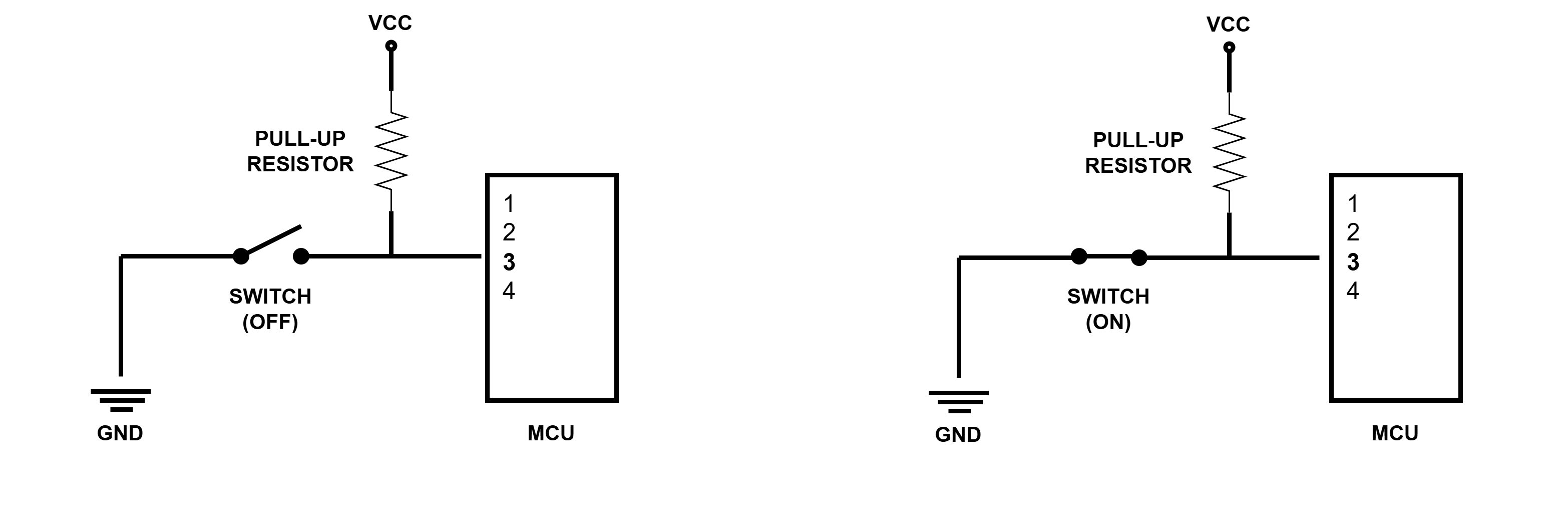
In this approach the resistor is very important as without it the button would connect VCC to ground, which is referred to as a short circuit and is very dangerous.
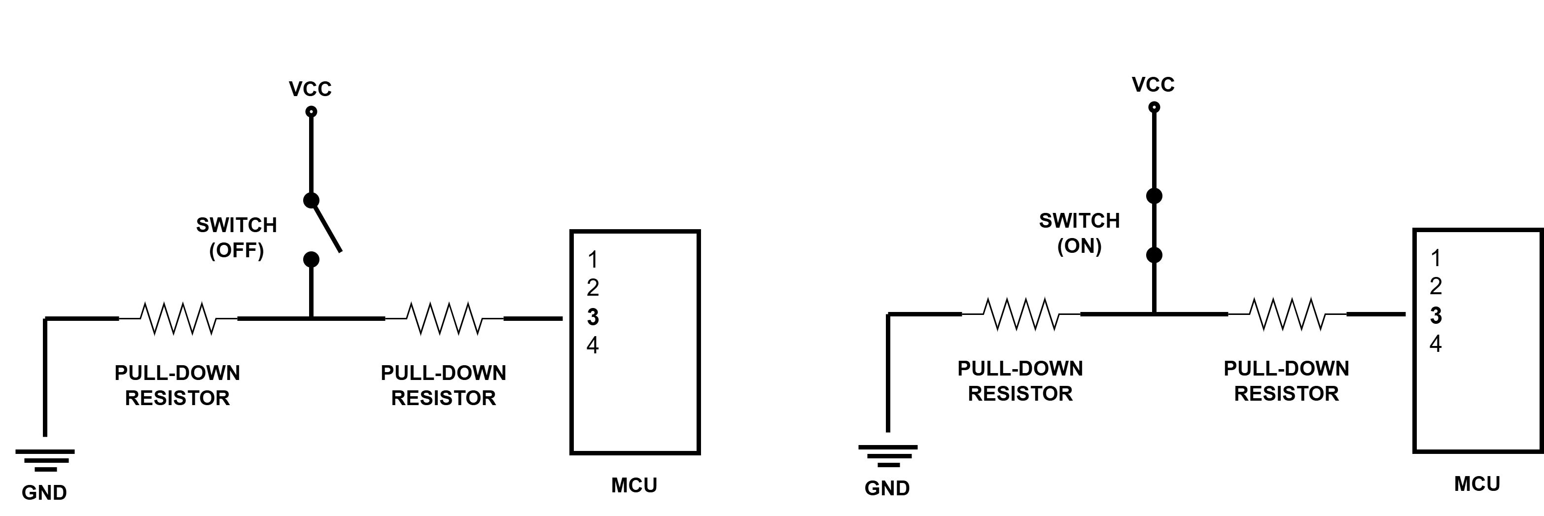
The reverse of a pull-up resistor would be a pull-down resistor. In this approach, as shown in the illustration below, the input pin is connected to the ground of the power supply through a resistor. When the switch is off, it connects the input pin directly to ground and has a clear 0V (and a LOW signal). When the switch is turned on a proper voltage and current (and a HIGH signal) is available on the pin.
Although the pull-up resistor approach is counter-intuitive, since you would normally expect a LOW signal when the button is off, it is more commonly used than the pull-down resistor. The microcontroller program should be coded accordingly.