Radio Frequency (RF)
The NRF24L01 is a wireless transceiver (transmitter and receiver) module used with Arduino boards to provide circuits the capability to communicate with other circuits using Radio Frequency (RF).
It is a half-duplex transceiver, which means that at the exact same moment in time it can either transmit or receive data, not both. But it can switch between transmit and receive modes very quickly, making communication appear simultaneous in most applications.
It uses the 2.4 GHz band and can operate with baud rates from 250 kbps to 2 Mbps. If used in open space and with a lower baud rate, its range can reach up to 100 meters.
Each module can communicate with 6 other modules. Using this capability, you can create a network of boards that communicate with each other directly. In IoT solutions, where boards are close to each other (such as in a Smart Home) radio can be an effective communication protocol without requiring WiFi infrastructure.
The nRF24L01 module is very useful but a bit tricky to set up and program. While the instructions and the sketch to set up microcontrollers to communication using radio work perfectly fine, they may function a bit erratically in practice.
NRF24L01 Pipes and Addresses
NRF24L01 modules (radios) have six “pipes” (virtual pipes managed by the device firmware, with no physical part) used for sending or receiving data to and from other radios. Pipe 0 is used to send (or write) data and is the “writing pipe”. Pipes 1 to 5 are used to receive (or read) data and are the “reading pipes”. Pipe 0 may be used for reading as well, but to minimize complexity, we will keep it as a dedicated writing pipe.
The number of pipes as used above means that one radio can send to any other radio (in sequence, not at the same time) and can listen to five other radios at the same time to receive the data they send. Each pipe has an “address”. A radio specifies addresses for the five pipes it is listening on, and other radios must send data to one of those five addresses.
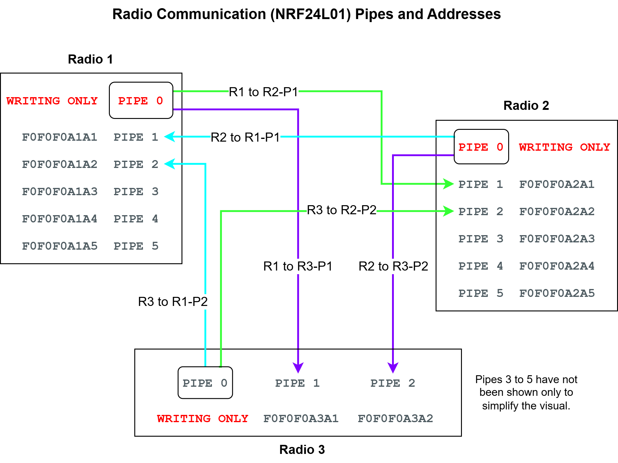
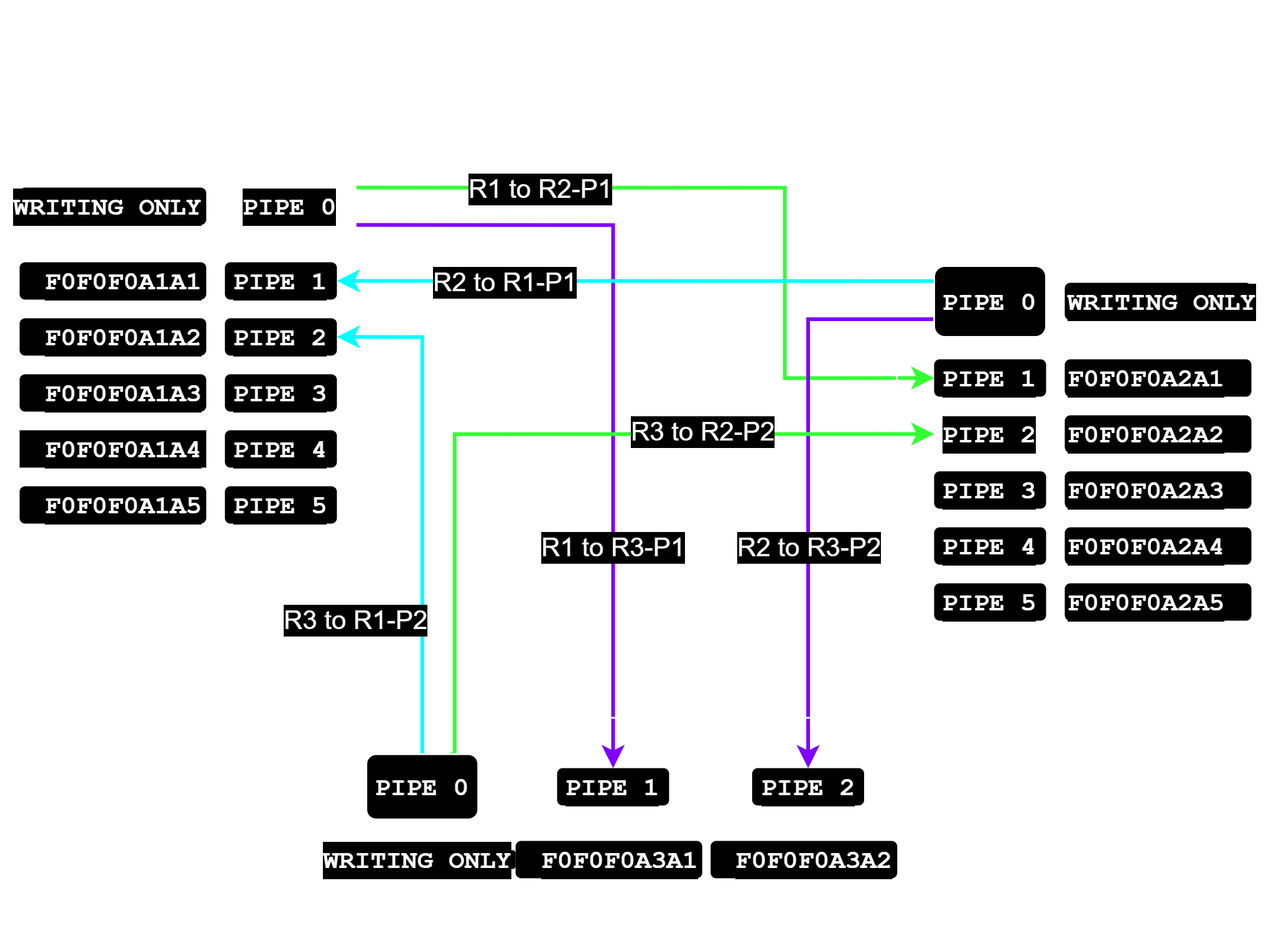
The NRF24L01 modules typically use a 40-bit address format, requiring 5-bytes of storage space per address. For a radio, pipes 1 to 5 should have addresses that differ only in the least significant (right-most) byte. In a set of radios that exchange data, each pipe address must be unique.
The listening pipe address configuration for three radio modules using the HEX format is shown in the table below. While any addressing convention can be used, we use the following: The first three bytes are all F0. The fourth bytes are A1 and A2 for circuits/radios 1 and 2. And the fifth byte is A1 to A5 for pipes 1 to 5.
** Radio 1**
| Pipe | Address |
|---|---|
| Pipe 0 | Writing only, no address |
| Pipe 1 | F0F0F0A1A1 |
| Pipe 2 | F0F0F0A1A2 |
| Pipe 3 | F0F0F0A1A3 |
| Pipe 4 | F0F0F0A1A4 |
| Pipe 5 | F0F0F0A1A5 |
** Radio 2**
| Pipe | Address |
|---|---|
| Pipe 0 | Writing only, no address |
| Pipe 1 | F0F0F0A2A1 |
| Pipe 2 | F0F0F0A2A2 |
| Pipe 3 | F0F0F0A2A3 |
| Pipe 4 | F0F0F0A2A4 |
| Pipe 5 | F0F0F0A2A5 |
The pipes used for communicating between radios must be pre-defined and fixed. The transmitting radio must agree with the receiving radio which of the receiver’s reading pipes it should send data on. The receiver radio expects data from any one specific transmitting radio on each of its pipes. For a radio that intends to transmit, pipe 0 is the fixed writing pipe so avoid listening on that.
Components
Both the transmitter and the receiver circuits will use the components listed below.
| Component | Purpose |
|---|---|
| NRF24L01 | The Radio module |
Circuit Diagram
Connections
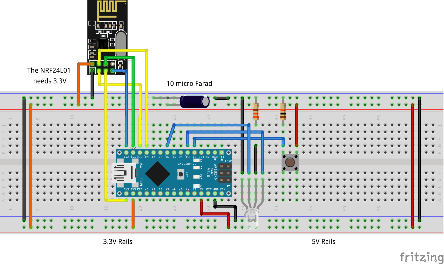
The NRF24L01 needs a 3.3V supply voltage and has the same operating voltage. But all pins on this module are 5V tolerant which means the module can be connected to an Arduino Nano without using a bi-directional level shifter. Any kind of noise in the power supply can interfere with the radio, so we need to connect a 10uF and 0.1uF capacitor in parallel to the VCC and Ground pins.
The module communicates with the board over the Serial Peripheral Interface (SPI) protocol.
In this project, the circuits/radios will use the following pipes to exchange data with each other.
| Transmitter | Receiver | Receiver Pipe Address |
|---|---|---|
| Radio 1 | Radio 2 | F0F0F0A2A1 |
| Radio 2 | Radio 1 | F0F0F0A1A1 |
Code
For transceiver (node) 1:
/*
  Project: NRF24L01 Radio Communication
  Project Description: This sketch receives and sends data from and to another circuit with the NRF24L01 module.

  Author: STEMVentor Educonsulting

  This code is copyrighted. Please do not reuse or share for any purpose other than for learning with subscribed STEMVentor programs. This code is for educational purposes only and is not for production use.
*/

/*
 *  LIBRARIES
 */

/* For RF communication using the nRF24L01:
 * TMRh20/RF24, https://github.com/tmrh20/RF24/
 *
 * For ESP32 the RF24 library needs a small modification:
 * https://github.com/nRF24/RF24/issues/393
 *
 * In file RF24_config.h add the following code just after line 135:
 *
 * #elif defined (ESP32)
 * #include <pgmspace.h>
 * #define PRIPSTR "%s"
 */

#include <SPI.h>
#include <nRF24L01.h>
#include <RF24.h>

/*
 * PIN DEFINITIONS
 */

/* For nRF24L01 with Arduino Nano*/
#define CE_PIN 9
#define CSN_PIN 10

/*
 * VARIABLE DEFINITIONS
 */

/*
 * RF device pipe addresses:
 * Read http://tmrh20.blogspot.com/2016/08/rf24-addressing-review-of-nrf24l01.html
 * Up to 6 pipes can be open for reading at once.
 * Open all the reading pipes, and then call startListening().
 * Pipe 0 doubles as the default writing pipe.
 * So if you open pipe 0 for reading, do an openWritingPipe() again before write().
 * To be safe, use only pipes 1-5 for reading.
 *
 * Addresses are assigned via a 5-byte array
 * For a radio, pipess 1-5 should have addresses that differ only in the least significant (right-most) byte.
 *
 * READING PIPES:
 * Radio 1 (Master): F0F0F0A1A1, F0F0F0A1A2
 * Radio 2 (Slave 1): F0F0F0A2A1, F0F0F0A2A2
 * Radio 3 (Slave 2): F0F0F0A3A1, F0F0F0A3A2
 *
 * WRITING PIPES:
 * Radio 1 (Master) to Radio 2 (Slave 1): F0F0F0A2A1
 * Radio 1 (Master) to Radio 3 (Slave 2): F0F0F0A3A1
 * Radio 2 (Slave 1) to Radio 1 (Master): F0F0F0A1A1
 * Radio 3 (Slave 2) to Radio 1 (Master): F0F0F0A1A2
 *
 * This can continue from any radio to any other radio
 * Prefix HEX values with 0x and suffix with LL to store as unit64_t
 */

/* To write to Node 2 */
const uint64_t writing_pipes[2] = { 0xF0F0F0A2A1LL, 0xF0F0F0A3A1LL };
/* To read from Node 1 */
const uint64_t reading_pipes[2] = { 0xF0F0F0A1A1LL, 0xF0F0F0A1A2LL };


/* Allocate space for incoming and outgoing data */
char RFSerial_data_in[32]; //For data received via RF
char RFSerial_data_out[32]; //For data to be sent via RF

/*
 * INSTANCE/OBJECT DEFINITIONS
 */

RF24 radio(CE_PIN,CSN_PIN); //The client object for RF communication

// Function to initialize radio communication.
void initRadio() {

  Serial.println("Initializing NRF24L01 Radio...");

  /* Initialize RF communication */
  radio.begin();

  Serial.println("NRF24L01 Radio Initialized!");

  /* Set power level of the radio */
  radio.setPALevel(RF24_PA_LOW);
  //radio.setPALevel(RF24_PA_MIN);
  /* Set RF data rate - lowest rate for longest range capability */
  radio.setDataRate(RF24_250KBPS);
  /* Set radio channel to use - ensure all slaves match this */
  radio.setChannel(0x66);
  /* Set time between retries and max retries */
  radio.setRetries(4, 10);
  /* Enable ackpayload - enables each slave to reply with data. Not used. */
  //radio.enableAckPayload();

  /* Open reading pipes and start listening */
  radio.openReadingPipe(1, reading_pipes[0]); // Listen to Node 2
  radio.openReadingPipe(2, reading_pipes[1]); //
  radio.startListening();

  Serial.println("Listening...");
}

/*
 * Function to send a radio signal.
 */

void sendToRFNode(uint8_t node_id, char node_data[32]) {
  // For some reason we cannot use the char[] passed as a parameter
  // It must be copied into a local char[]
  char node_data_copy[32] = "";
  strcpy(node_data_copy, node_data);

  // Since we have a dedicated writing pipe, no need to call stopListening().
  // Calling it anyway to be safe, ensure startListening() is called as required.
  radio.stopListening();

  // Display status on the serial monitor
  Serial.println("Sending: " + (String)node_id + "|" + (String)node_data_copy);
  Serial.print(F("Sending to node: "));
  Serial.println(node_id);

  radio.openWritingPipe(writing_pipes[node_id-1]); //Subtract 1 from the node_id since array index start from 0

  /* Send RF data */
  if (!radio.write( &node_data_copy, sizeof(node_data_copy) )){
    Serial.println("Failed!");
    Serial.println(node_data_copy);
  }
  else{
    Serial.println("Sent!");

    //DEBUG
    Serial.print(F("Sent: "));
    Serial.println(node_data_copy);
  }
}

/*
 * Function to receive a radio signal.
 */
void readFromRFNode() {

  uint8_t pipeNum;
    //No need to open the reading pipe everytime
   //Unless you have switched to writing on the reading pipes no need to start listening.
   //However, since, to be safe, stopListening() is being called when writing data
   //need to call startListening() here.
  radio.startListening();

  /*
   * Set up a timeout period, and break after the period...
   * so other listeners can be polled in the loop()
   */

  /* Get the current time in microseconds */
  unsigned long started_waiting_at = micros();
  /* Variable to indicate if a response was received or not */
  boolean timeout = false;

  /* While nothing is received */
  while ( !radio.available(&pipeNum) ){
    /* If waited longer than 200ms, indicate timeout and exit while loop */
    if (micros() - started_waiting_at > 200000 ){
        timeout = true;
        break;
    }
  }
  // Print data to serial monitor
  if ( timeout ){
      Serial.print(F("."));
  }else{
      /* Grab the response, compare, and send to debugging spew */
      char node_data[32];
      radio.read( &node_data, sizeof(node_data) );

      unsigned long recv_time = micros();

      /* Spew it to console for debugging */
      Serial.println(F("."));
      Serial.print(F("Got message: "));
      Serial.print(node_data);
      Serial.print(F(", From pipe: "));
      Serial.print(pipeNum);
      Serial.print(F(", Received at: "));
      Serial.print(recv_time);
      Serial.println(F(" microseconds"));

      //Display data on the serial monitor
      Serial.print("Data received: ");
      Serial.println((String)node_data);
  }
}

// The setup function runs once when you press reset or power the board.
void setup() {
  Serial.begin(115200); //The default serial port for communication with serial monitor.

  //Initialize radio communication
  initRadio();
}

 // The loop function runs over and over again forever with a delay of 10 seconds
void loop() {

  /* Send RF data */
  /* Basic test: Get system time and send it. This will block until complete */
  /*
  unsigned long start_time = micros();
  if (!radio.write( &start_time, sizeof(unsigned long) )){
    Serial.println(F("Sending signal failed."));
  }
  else{
    Serial.println(F("Sent signal successfully."));
  }
  */

  /*
   * Open the RF listening port and listen for a while then break
   * so other listeners can be polled in the loop()
   */
  readFromRFNode();

  /* Construct the data string that needs to be send to the node with node_id */
  /* First reset the string variable */
  RFSerial_data_out[0] = '\0';

  strcat(RFSerial_data_out, "Test string");

  /* Send data over RF to the slave node depending on the incoming data values */
  sendToRFNode(2, RFSerial_data_out);

  delay(15*1000);
}
For transceiver (node) 2:
/*
  Project: NRF24L01 Radio Communication
  Project Description: This sketch receives and sends data from and to another circuit with the NRF24L01 module.

  Author: STEMVentor Educonsulting

  This code is copyrighted. Please do not reuse or share for any purpose other than for learning with subscribed STEMVentor programs. This code is for educational purposes only and is not for production use.
*/

/*
 *  LIBRARIES
 */

/* For RF communication using the nRF24L01:
 * TMRh20/RF24, https://github.com/tmrh20/RF24/
 *
 * For ESP32 the RF24 library needs a small modification:
 * https://github.com/nRF24/RF24/issues/393
 *
 * In file RF24_config.h add the following code just after line 135:
 *
 * #elif defined (ESP32)
 * #include <pgmspace.h>
 * #define PRIPSTR "%s"
 */

#include <SPI.h>
#include <nRF24L01.h>
#include <RF24.h>

/*
 * PIN DEFINITIONS
 */

/* For nRF24L01 with Arduino Nano*/
#define CE_PIN 9
#define CSN_PIN 10

/*
 * VARIABLE DEFINITIONS
 */

/*
 * RF device pipe addresses:
 * Please see radio_node1.ino for a detailed explanation
 */

// To write to Node 1
const uint64_t writing_pipes[2] = { 0xF0F0F0A1A1LL, 0xF0F0F0A3A2LL };
// To read from Node 2
const uint64_t reading_pipes[2] = { 0xF0F0F0A2A1LL, 0xF0F0F0A2A2LL };

// Allocate space for incoming and outgoing data
char RFSerial_data_in[32]; //For data received via RF
char RFSerial_data_out[32]; //For data to be sent via RF


/*
 * INSTANCE/OBJECT DEFINITIONS
 */

RF24 radio(CE_PIN,CSN_PIN); //The client object for RF communication

// Function to initialize radio communication.
void initRadio() {

  Serial.println("Initializing NRF24L01 Radio...");

  /* Initialize RF communication */
  radio.begin();

  Serial.println("NRF24L01 Radio Initialized!");

  /* Set power level of the radio */
  radio.setPALevel(RF24_PA_LOW);
  //radio.setPALevel(RF24_PA_MIN);
  /* Set RF data rate - lowest rate for longest range capability */
  radio.setDataRate(RF24_250KBPS);
  /* Set radio channel to use - ensure all slaves match this */
  radio.setChannel(0x66);
  /* Set time between retries and max retries */
  radio.setRetries(4, 10);
  /* Enable ackpayload - enables each slave to reply with data. Not used. */
  //radio.enableAckPayload();

  // Open reading pipes and start listening
  radio.openReadingPipe(1, reading_pipes[0]); //Listen to Node 1
  radio.openReadingPipe(2, reading_pipes[1]);
  radio.startListening();

  Serial.println("Listening...");
}

/*
 * Function to send a radio signal.
 */

void sendToRFNode(uint8_t node_id, char node_data[32]) {
  // For some reason we cannot use the char[] passed as a parameter
  // It must be copied into a local char[]
  char node_data_copy[32] = "";
  strcpy(node_data_copy, node_data);

  // Since we have a dedicated writing pipe, no need to call stopListening().
  // Calling it anyway to be safe, ensure startListening() is called as required.
  radio.stopListening();

  // Display status on the serial monitor
  Serial.println("Sending: " + (String)node_id + "|" + (String)node_data_copy);
  Serial.print(F("Sending to node: "));
  Serial.println(node_id);

  radio.openWritingPipe(writing_pipes[node_id-1]); //Subtract 1 from the node_id since array index start from 0

  /* Send RF data */
  if (!radio.write( &node_data_copy, sizeof(node_data_copy) )){
    Serial.println("Failed!");
    Serial.println(node_data_copy);
  }
  else{
    Serial.println("Sent!");

    //DEBUG
    Serial.print(F("Sent: "));
    Serial.println(node_data_copy);
  }
}

/*
 * Function to receive a radio signal.
 */
void readFromRFNode() {

  uint8_t pipeNum;
    //No need to open the reading pipe everytime
   //Unless you have switched to writing on the reading pipes no need to start listening.
   //However, since, to be safe, stopListening() is being called when writing data
   //need to call startListening() here.
  radio.startListening();

  /*
   * Set up a timeout period, and break after the period...
   * so other listeners can be polled in the loop()
   */

  /* Get the current time in microseconds */
  unsigned long started_waiting_at = micros();
  /* Variable to indicate if a response was received or not */
  boolean timeout = false;

  /* While nothing is received */
  while ( !radio.available(&pipeNum) ){
    /* If waited longer than 200ms, indicate timeout and exit while loop */
    if (micros() - started_waiting_at > 200000 ){
        timeout = true;
        break;
    }
  }
  // Print data to serial monitor
  if ( timeout ){
      Serial.print(F("."));
  }else{
      /* Grab the response, compare, and send to debugging spew */
      char node_data[32];
      radio.read( &node_data, sizeof(node_data) );

      unsigned long recv_time = micros();

      /* Spew it to console for debugging */
      Serial.println(F("."));
      Serial.print(F("Got message: "));
      Serial.print(node_data);
      Serial.print(F(", From pipe: "));
      Serial.print(pipeNum);
      Serial.print(F(", Received at: "));
      Serial.print(recv_time);
      Serial.println(F(" microseconds"));

      //Display data on the serial monitor
      Serial.print("Data received: ");
      Serial.println((String)node_data);
  }
}

// The setup function runs once when you press reset or power the board.
void setup() {
  Serial.begin(115200); //The default serial port for communication with serial monitor.

  //Initialize radio communication
  initRadio();
}

 // The loop function runs over and over again forever with a delay of 10 seconds
void loop() {
   //Open the RF listening port and listen for a while then break
   //so other things can be done in the loop()
  readFromRFNode();

  /* Construct the data string that needs to be send to the node with node_id */
  /* First reset the string variable */
  RFSerial_data_out[0] = '\0';

  strcat(RFSerial_data_out, "Test string");

  /* Send data over RF to the slave node depending on the incoming data values */
  sendToRFNode(1, RFSerial_data_out);

  delay(15*1000);
}