Potentiometer
This project demonstrates how to read an analog input from a Potentiometer and use it to control the brightness of an external LED using a microcontroller.
A potentiometer has a shaft that can be turned with a knob or a screw. Turning the shaft changes the amount of internal resistance, which changes the voltage ouput at the center pin. The varying voltage is read by the analog input pin on the Arduino board. Arduino boards have a circuit inside called an analog-to-digital converter (ADC) that reads a voltage that varies from 0V to 5V and proportionately converts it to a number between 0 and 1023.
Pulse Width Modulation
Arduino boards do not have a dedicated Digital to Analog converter. Instead, they generate analog signals using a technique known as Pulse Width Modulation (PWM). In PWM the digital signal is sent as a square wave, achieved by switching between on and off. This on-off pattern can simulate voltages between 0V and the maximum possible for the board (generally 3.3V or 5V) by changing the time the signal is on and off at a certain frequency. The time the signal is on is referred to as the pulse width (or duty cycle). To get varying analog values, you change, or modulate, the pulse width.
PWM essentially controls the average power delivered by an electrical signal. The frequency of the pulse should generally be at a rate faster than it takes the load to change significantly. PWM is used to control the brightness of an LED or the speed of a motor.

Most boards only support PWM output on a few pins, generally indicated by a tilde (~) symbol.
Components
| Component | Purpose |
|---|---|
| Arduino Nano | The microcontroller |
| 3 pin potentiomter | The potentiometer |
| 2 pin LED | The LED for which the brightness will be controlled |
Circuit Diagram
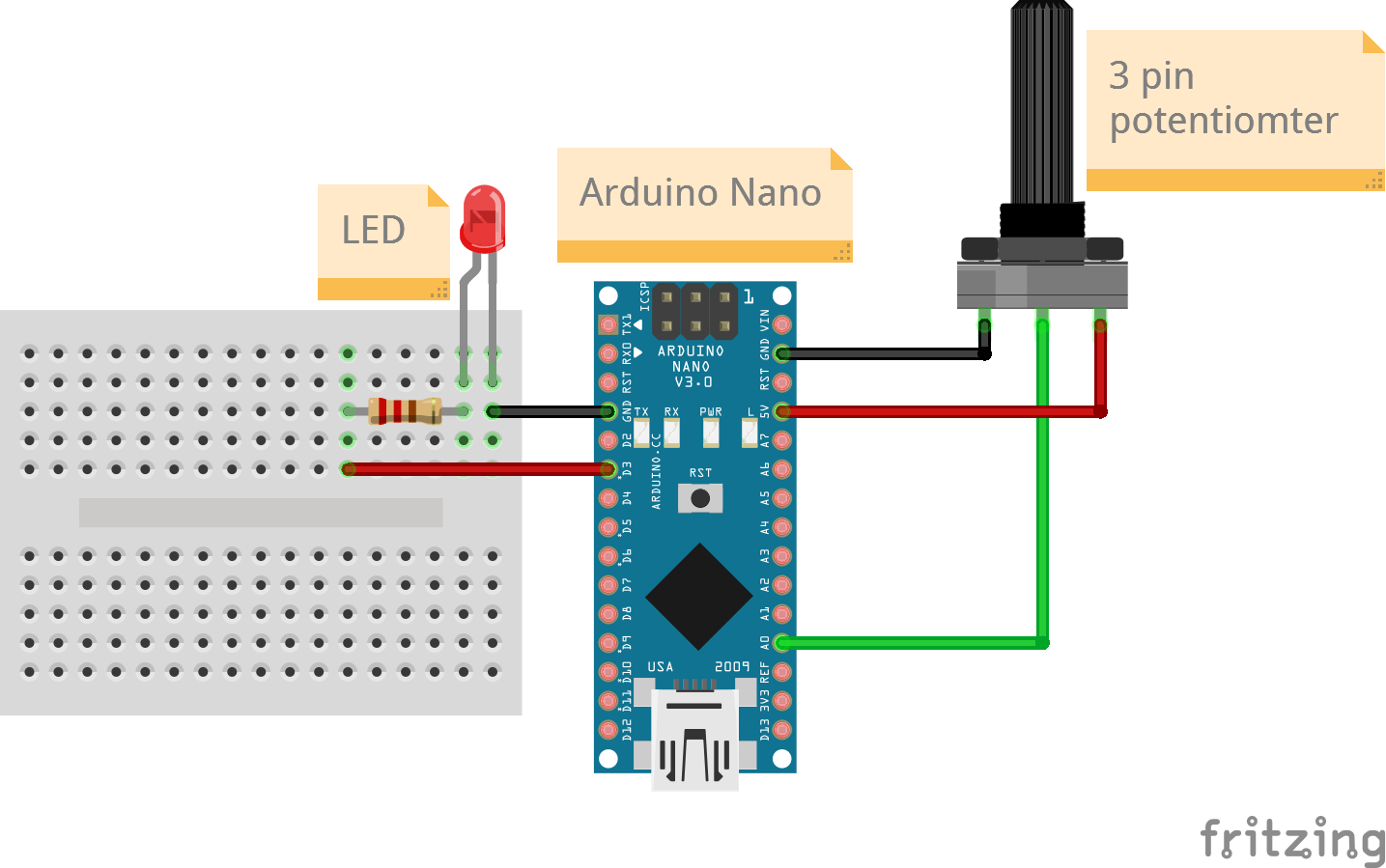
Connections
3 Pin potentiometer
| Arduino Nano Pin | Potentiometer Pin |
|---|---|
| A0 | Output |
| 5v | 5V |
| GND | GND |
2 pin LED
For an LED the longer pin is the anode (+ve) and is connected to the signal pin while the shorter pin is the cathode (-ve) and is connected to ground.
Always add a resistor in series with the LED to reduce the current flowing through the LED, especially if the LED will be on continously. This is to prevent early burnout of the LED. Select the resistance value depending on the LED brightness you need.
| Arduino Nano Pin | LED Pin |
|---|---|
| D3 (PWM) | Anode (longer leg) |
| GND | Cathode (shorter leg) |
Code
/*
  Project: Physical Computing
  Circuit: Potentiometer-LED
  Boards Supported: UNO R3/R4, Nano, ESP32
  Function: Reads a varying voltage from a potentiometer and controls the brightness of an LED.

  Author: STEMVentor Educonsulting

  This code is copyrighted. Please do not reuse or share for any purpose other than for learning with subscribed STEMVentor programs. This code is for educational purposes only and is not for production use.
*/

// LIBRARIES

// PIN DEFINTIONS
#LED_PIN 3 // Must be a PWM pin
#POTENTIOMETER_PIN A0

// CONSTANT DEFINITIONS

// GLOBAL VARIABLES
uint8_t potentiometer_value;
uint8_t brightness;

// INITIALIZE OBJECTS

// LOCAL FUNCTIONS
void ledSetup()
{
  // Set the LED pin mode to output.
  pinMode(LED_PIN, OUTPUT);
  // digitalWrite() can only send two values (HIGH or LOW) to a pin.
  digitalWrite(LED_PIN, LOW);
}

void potentiometerSetup()
{
  // initialize the Potentiometer pin as an input.
  pinMode(POTENTIOMETER_PIN, INPUT);
}

void readPotentiometer()
{
  // Read the value of the Potentiometer state.
  potentiometer_value = analogRead(POTENTIOMETER_PIN);
  Serial.print("Potentiometer value: ");
  Serial.println(potentiometer_value);

  // For Arduino Nano
  // analogRead returns a number between 0 and 1024 while analogWrite takes a number between 0-255
  // Use the map function to do the proportional conversion.
  brightness = map(potentiometer_value, 0, 1024, 0, 255);

  // For ESP32
  // analogRead returns a number between 0 and 4098
  // brightness = map(potentiometerValue, 0, 4098, 0, 255);

  Serial.print("Brightness value: ");
  Serial.println(brightness);
}

void analogWriteLed(int value)
{
  // analogWrite() can send values from 0 to 255 to a pin (must be a PWM pin)
  // which will send a varying voltage to the attached component.
  // Note that the analogWrite() function has nothing to do with the analog pins or the analogRead() function.
  // Those are for analog input only.
  analogWrite(LED_PIN, value);
}

// THE setup FUNCTION RUNS ONCE WHEN YOU PRESS RESET OR POWER THE BOARD.
void setup()
{
  // Start the serial communication with baud rate suitable for your components.
  Serial.begin(9600);
  ledSetup();
  potentiometerSetup();
  Serial.println("The board is ready!");
}

// THE loop FUNCTION RUNS OVER AND OVER AGAIN FOREVER UNTIL THE BOARD IS POWERED OFF.
void loop()
{
  readPotentiometer();
  analogWriteLed(brightness);
  delay(1000);
}