LCD Connections
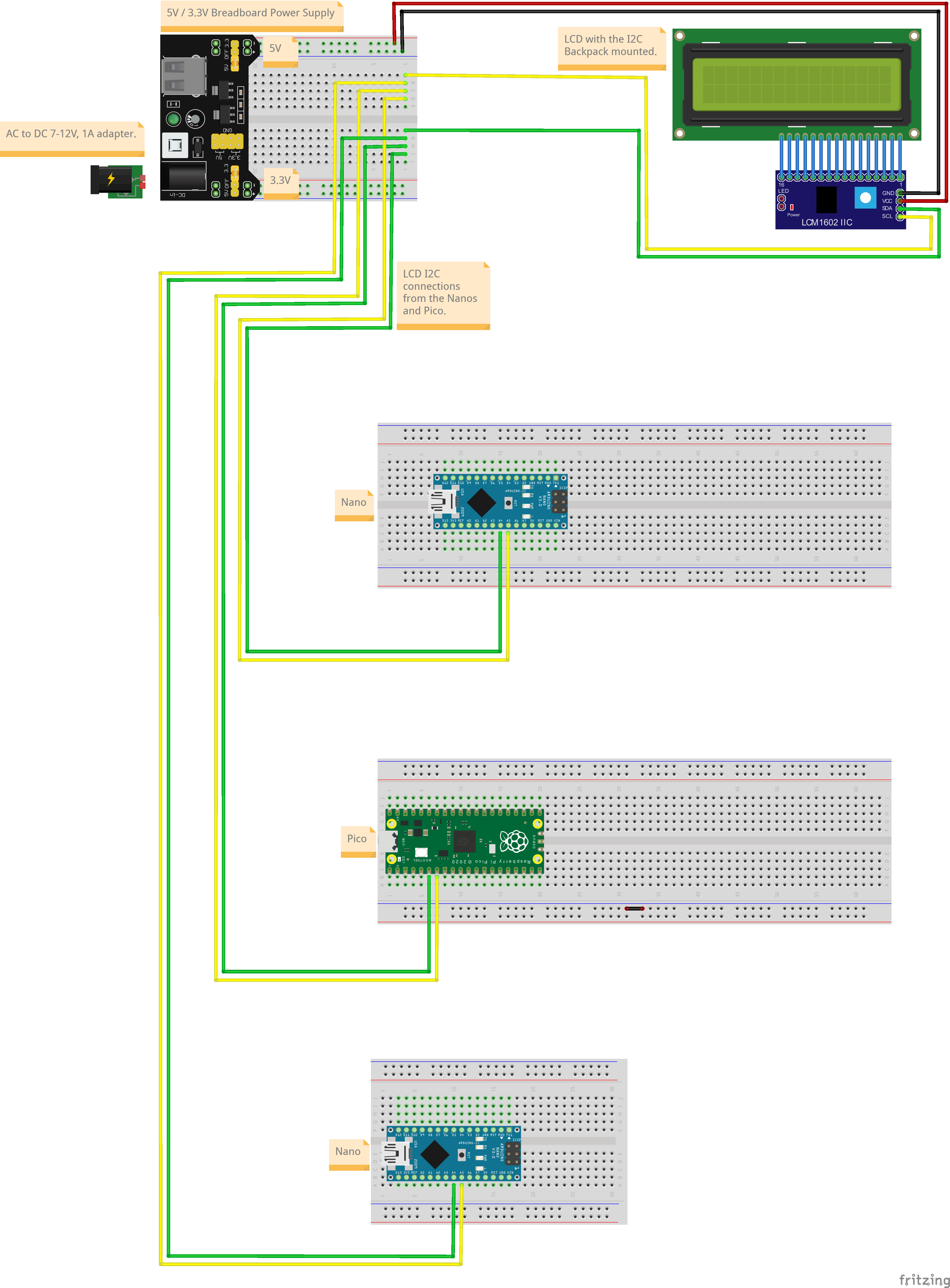
The two Nanos and the Pico will be using a shared LCD, the connections for which are shown below. The ESP32 will be using an OLED and will not be connected to the shared LCD.
Connections
Board pin numbers are those printed on the board while code pin numbers need to be used in code (generally indicated in the pinout diagram as the GPIO pin number). They may be the same or different, depending on the board.
Nano Input Circuit
Board Pin | Code Pin | Pin Mode | Component | Pin |
|---|---|---|---|---|
| A4 | A4 | I2C SDA | I2C lCD | SDA |
| A5 | A5 | I2C SCL | I2C LCD | SCL |
Nano Sensor and Controller Circuit
Board Pin | Code Pin | Function | Component | Pin |
|---|---|---|---|---|
| A4 | A4 | I2C SDA | I2C LCD | SDA |
| A5 | A5 | I2C SCL | I2C LCD | SCL |
Pico Sensor and Controller Circuit
Board Pin | Code Pin | Mode | Component | Pin |
|---|---|---|---|---|
| 6 | 4 | I2C SDA | I2C LCD | SDA |
| 7 | 5 | I2C SCL | I2C LCD | SCL |
Connection Diagram

Code
The code for this circuit is distributed across multiple files, so will not be displayed here. It will be available for download for subscribers.