Relay
A relay is an electrically operated switch that can be turned on or off, letting the current go through or not, and can be controlled with low voltages, like the 5V provided by the Arduino pins.
A relay is an electrically operated switch. It consists of a pair of input terminals (+ve and -ve terminals) on one side and a couple of mechanical contact switch terminals on the other side. One electrical circuit (control circuit) is connected on the input side, and another electrical circuit (controlled circuit) is connected on the other side. The control circuit can send a high voltage or an electrical signal to the input terminals, which will then change the position of the mechanical contact switch (opening it or closing it) to open or close the controlled circuit and turn the controlled device ON/OFF.
Generally, a low-voltage electronic circuit is used to control a high-voltage electrical circuit. Relays are therefore extensively used in IoT projects, where, using an electronic circuit with a microprocessor, you can control your electrical home light bulbs and other appliances. The traditional form of a relay uses an electromagnet to close or open the switch contacts. However, other operating principles have been invented, like in solid-state relays using semiconductor properties to control without relying on moving parts.
The switch (controlled) side of a relay is often designed to be available in two operating modes: Normally Open (NO) and Normally Closed (NC). In a normally open relay, the controlled circuit is open by default, so we can say a lightbulb connected in that circuit will be off. But when the control circuit sends a high voltage signal to indicate the switch is closed and the lightbulb turns on. In a normally closed relay, it works in a reverse manner. The controlled circuit is closed by default, so we can say a lightbulb connected in that circuit will be on. When the control circuit sends a high voltage signal, the switch is opened, and the lightbulb turns off. In an IoT solution, where an electronic circuit needs to control a physical object, for example, close a door, a combination of relays and actuators is used. The control signal from the electronic circuit will switch the actuator circuit on or off, and the actuator will perform the action for which it is designed.
The illustration shows how a relay works:

The relay module shown above has two channels (the blue cubes). Modules with one, four, and eight channels are also available. This module is powered with 5V, which makes it appropriate to use with an Arduino. You can also get relay modules powered with 3.3V, which is ideal for an ESP32.
Each channel has a high voltage side connected to the electrical appliance the relay is controlling and a low voltage side connected to the microcontroller controlling the relay.
The high-voltage side of each channel has three sockets/pins:
-
COM: Common pin to which you connect the neutral wire (in any electrical circuit there are two wires one the carries the electric current known as the live wire and the other is the neutral wire) to the electrical appliance.
-
NC (Normally Closed): the normally closed configuration is used when you want the relay to be closed by default, meaning the current is flowing (and the connected appliance is powered on) until you send a signal from the microcontroller to the relay module to open the circuit and stop the current (and switch off the connected appliance).
-
NO (Normally Open): This configuration works the other way around from NC. The relay is always open, so the circuit is broken (and the connected device is powered off) until you send a signal from the microcontroller to close the circuit (and switch on the connected device).
The low-voltage side of each channel has the VCC and GND pins to power up the module and a third pin which is the input pin to send the control signal for each channel (IN1 and IN2 in this module).
The module has a jumper cap connecting the VCC and JD-VCC pins. The jumper cap allows you to choose whether the circuit is physically connected to the Arduino circuit or not. With the jumper cap on, the VCC and JD-VCC pins are connected. That means the relay electromagnet is directly powered from the Arduino’s power pin, so the relay module and the Arduino circuits are not physically isolated from each other. Without the jumper cap, you need to provide an independent power source to power up the relay’s electromagnet through the JD-VCC pin. This configuration physically isolates the relays from the Arduino with the module’s built-in optocoupler.

Project
This project enables control of a 5V relay based on input received through the serial monitor. Users can input either ‘1’ to switch the relay on or ‘0’ to switch it off via the serial monitor.
Components
| Component | Purpose |
|---|---|
| Arduino Nano | This will be the microcontroller |
| 1 channel 5V relay | This will be the relay |
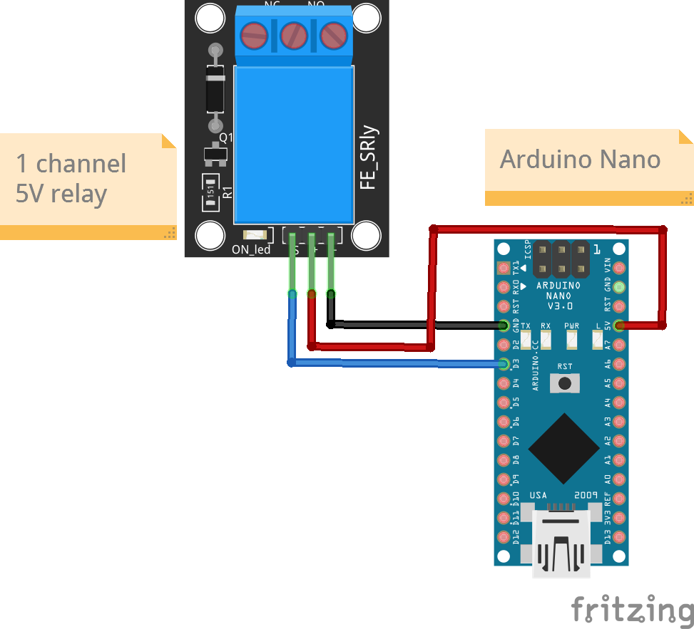
Circuit Diagram
Connections
| Nano Pin | Relay Pin |
|---|---|
| D4 | Sig |
| 5V | VCC |
| Gnd | Gnd |
Code
/*
  Project: Serial input with output as relay
  Project Description:
  This sketch writes readings reads from serial and accordingly switches a relay on or off.
  This sketch is for a 5v relay

  Author: STEMVentor Educonsulting

  This code is copyrighted. Please do not reuse or share for any purpose other than for learning with subscribed STEMVentor programs.
  This code is for educational purposes only and is not for production use.
*/

// LIBRARIES

// PIN DEFINITIONS
#define RelayPin 4
// CONSTANT DEFINITIONS

// GLOBAL VARIABLES
// Used for reading by character.
// Note that the 64 byte size of the Arduino serial input buffer does not limit the number of characters that you can receive
// because the code can empty the buffer faster than new data arrives.

// Used for reading an integer value.
int receivedString;

// LOCAL FUNCTIONS

// Read an entire string (this is a blocking function and waits until timeout).
void readString(){
  Serial.println("Enter 1 to switch on the relay");
  Serial.println("Enter 0 to switch off the relay");
  // Wait until data is available
  while (!Serial.available()) {}

  // Read characters until newline is encountered
  String input = Serial.readStringUntil('\n');

  // Convert the input string to an integer
  receivedString = input.toInt();

  // Print the entered value for confirmation
  Serial.print("Entered value: ");
  Serial.println(receivedString);

  // Clear the input buffer to prevent trailing characters
  while (Serial.available()) {
    Serial.read(); // Read and discard any remaining characters
  }
}

void digitalWriteRelay(int value)
{
  if ( value == 1){
    digitalWrite(RelayPin , HIGH);
    Serial.println("Relay is switched on");

  }

  else if ( value == 0){
    digitalWrite(RelayPin , LOW);
    Serial.println("Relay is switched off");
  }

  else {
    Serial.println("Invalid input");
  }
}

void relaySetup()
{
  // Define relay pin mode
  pinMode(RelayPin , OUTPUT);
  digitalWrite(RelayPin , LOW);
}
// THE setup FUNCTION RUNS ONCE WHEN YOU PRESS RESET OR POWER THE BOARD.
void setup() {
  Serial.begin(9600);
  relaySetup();
  Serial.println("The board is ready!");
}

// THE loop FUNCTION RUNS OVER AND OVER AGAIN FOREVER UNTIL THE BOARD IS POWERED OFF.
// Run only one option at a time (comment out all code for the other option).
void loop() {
  //  Read a string
  readString();
  digitalWriteRelay(receivedString);
}