Microcontroller Boards
Microcontrollers are often packaged as boards with connectors for sensors, controllers, displays, and other electronic components, and other components to simplify their use in building physical computing or IoT solutions.
While specifications vary across boards, they all generally have the following:
-
A Microprocessor:
This executes the instructions that tell the board what it needs to do. -
Memory:
Memory is used to store instructions and data. Memory can be volatile (the data is erased when the microcontroller is powered off) or non-volatile (the data is stored even when the microcontroller is powered off).Memory is categorized into two types:
- Flash/EEPROM (Erasable Programmable Read-Only Memory) which stores the instructions or programs.
- RAM (Random Access Memory) which stores the data used by the programs.
-
Serial communications interfaces:
Microcontrollers can be connected to a computer to upload programs and exchange data. Serial communication interfaces are used for that purpose. The serial communication happens through USB cables and through pins. Microcontrollers are pre-programmed with a boot loader that simplifies the uploading of programs to the on-chip flash memory. Boards are loaded with program code via a serial connection to another computer. -
Digital and analog input/output (I/O) pins
The boards are equipped with sets of pins that can be connected using wires to components or other boards or modules. Pins can provide digital or analog signals and can be used for General Purpose Input/Output (GPIO) or for specific functions.
Some GPIO (General-Purpose Input/Output) pins server other functions such as I2C, SPI, and UART communication. If you do not need these pins for their specific functions, you can use them for regular digital input/output, but otherwise, keep them free for their specific functions.
Some pins output a high or a low signal when the board boots up. Any active components connected to these chips will be affected. For example, an LED connected to a pin that outputs a high signal when booting up will light up.
A board makes available its microprocessor pins and may add some pins of its own for additional functionality. The pins on a board are labelled, generally using letters and numbers (such as D1, D2, and so on for digital pins, A1, A2, and so on for analog pins). When a pinout diagram or pin numbers are provided in specifications, it is important to know what pin they are referring to, the chip pin or the board pin. In most projects we will be using the board pins.
- A 5V or a 3.3V linear regulator
Arduino boards can be powered from your computer or with a DC supply or batteries. The onboard regulator maintains the voltage at the required level to prevent damage to the board.
Boards generally take a 5V input but the output voltage on the pins may be 5V or 3.3V. Only boards and components with the same voltage may be connected. If a higher voltage is supplied the board or component may get damaged and if a lower voltage is supplied they may not work reliably.
- USB Cable Connectors
These are used to allow the board to be connected to a computer from where the program can be uploaded. One important aspect of USB cables is that they are for charging only or for charging and data. For programming Arduino and other boards, you need cables that support charging and data. Data cables have four connector wires in the USB interface, while power cables have only two connector wires. It is not easy to differentiate between the two visually, so you must read the specifications thoroughly.
Popular Boards
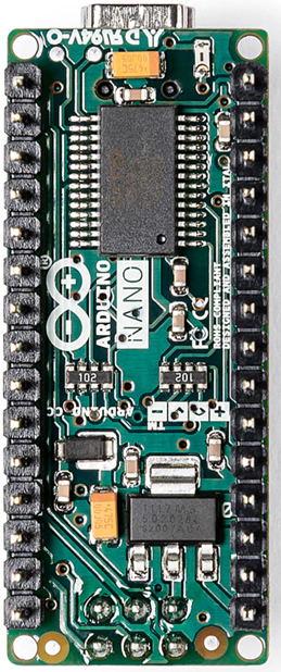
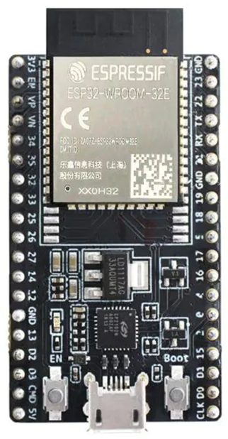
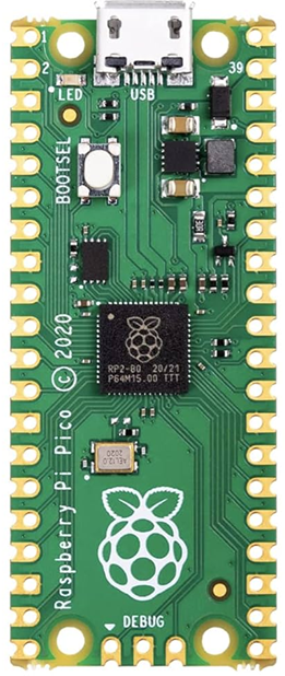
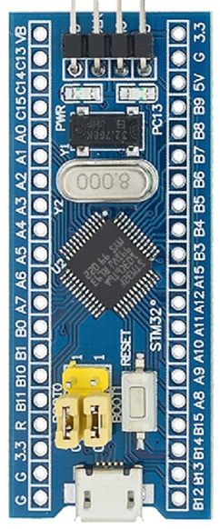
There are four microcontroller boards that are popularly used for learning to build Physical Computing and IoT solutions. These are shown below:
In addition to these there are two other boards that are quite popular.
-
The Arduino Uno which is very similar in function to the Arduino Nano. The Arduino Uno is not breadboard mountable and has a larger size that the Nano but also has more available pins.
-
The ESP8266 NodeMCU which is very similar in function to the ESP32 but only supports WiFi communication and not BLE communication.
Given these similarities we may specifically use these two boards in some projects but most projects will use one of the four boards listed first.