Radio Frequency (RF)
The NRF24L01 is a wireless transceiver (transmitter and receiver) module used with Arduino boards to provide circuits the capability to communicate with other circuits using Radio Frequency (RF). It uses the 2.4 GHz band and can operate with baud rates from 250 kbps to 2 Mbps. If used in open space and with a lower baud rate, its range can reach up to 100 meters.
Each module can communicate with 6 other modules. Using this capability, you can create a network of boards that communicate with each other directly. Such a network is known as a mesh network and reduces the dependency on a single router. In IoT solutions, where boards are close to each other (such as in a Smart Home) radio can be an effective communication protocol without requiring WiFi infrastructure.
The nRF24L01 module is very useful but a bit tricky to set up and program. While the instructions and the sketch to set up microcontrollers to communication using radio work perfectly fine, they may function a bit erratically in practice.
NRF24L01 Pipes and Addresses
NRF24L01 modules (radios) have six “pipes” (virtual pipes managed by the device firmware, with no physical part) used for sending or receiving data to and from other radios. Pipe 0 is used to send (or write) data and is the “writing pipe”. Pipes 1 to 5 are used to receive (or read) data and are the “reading pipes”. Pipe 0 may be used for reading as well, but to minimize complexity, we will keep it as a dedicated writing pipe.
The number of pipes as used above means that one radio can send to any other radios (in sequence, not at the same time) and can listen to five other radios at the same time to receive the data they send. Each pipe has an “address”. A radio specifies addresses for the five pipes it is listening on, and other radios must send data to one of those five addresses. The NRF24L01 modules typically use a 40-bit address format, requiring 5-bytes of storage space per address. For a radio, pipes 1 to 5 should have addresses that differ only in the least significant (right-most) byte. In a set of radios that exchange data, each pipe address must be unique.
The listening pipe address configuration for three radio modules using the HEX format is shown in the table below. While any addressing convention can be used, we use the following: The first three bytes are all F0. The fourth byte is A1, A3, and A3 for circuits/radios 1, 2, and 3 respectively. And the fifth byte is A1 to A5 for pipes 1 to 5 respectively.
| Pipe | Radio 1 Addresses |
|---|---|
| Pipe 0 | Writing only, no address |
| Pipe 1 | F0F0F0A1A1 |
| Pipe 2 | F0F0F0A1A2 |
| Pipe 3 | F0F0F0A1A3 |
| Pipe 4 | F0F0F0A1A4 |
| Pipe 5 | F0F0F0A1A5 |
| Pipe | Radio 2 Addresses |
|---|---|
| Pipe 0 | Writing only, no address |
| Pipe 1 | F0F0F0A2A1 |
| Pipe 2 | F0F0F0A2A2 |
| Pipe 3 | F0F0F0A2A3 |
| Pipe 4 | F0F0F0A2A4 |
| Pipe 5 | F0F0F0A2A5 |
| Pipe | Radio 3 Addresses |
|---|---|
| Pipe 0 | Writing only, no address |
| Pipe 1 | F0F0F0A3A1 |
| Pipe 2 | F0F0F0A3A2 |
| Pipe 3 | F0F0F0A3A3 |
| Pipe 4 | F0F0F0A3A4 |
| Pipe 5 | F0F0F0A3A5 |
The pipes used for communicating between radios must be pre-defined and fixed. The transmitting radio must agree with the receiving radio which of the receiver’s reading pipes it should send data on. The receiver radio expects data from anyone specific transmitting radio on each of its pipes. For a radio that intends to transmit, pipe 0 is the fixed writing pipe so avoid listening on that.
Components
Circuit Diagram
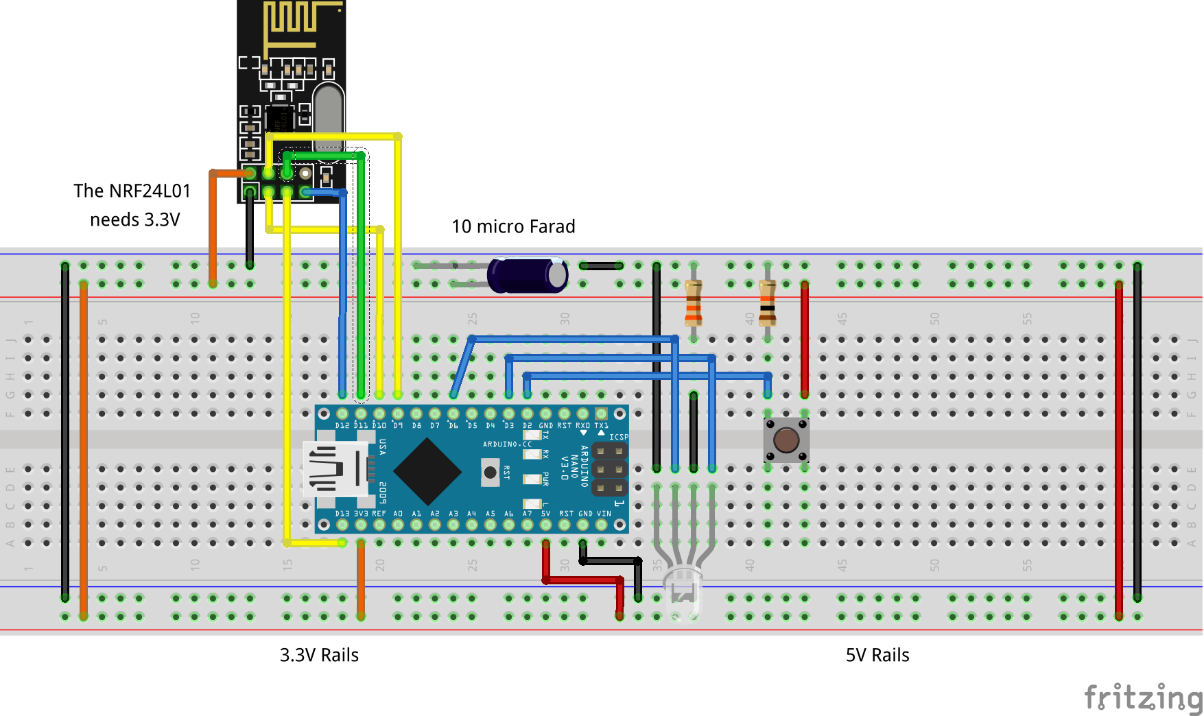
Connections
The NRF24L01 has a 3.3V operating voltage. When using it with a Nano, ensure it is connected to the 3.3V supply and not the 5V supply. Any kind of noise in the power supply can interfere with the radio, but this can be easily overcome by connecting a 10uF and 0.1uF capacitor in parallel to the Vcc and Ground pins.
It communicates with the board over the Serial Peripheral Interface (SPI) protocol, so pins D10 to D13, which are SPI pins on the Nano, need to be used.
The way an NRF24L01 module works and the concept of pipes and addresses required for RF communication between modules is explained in detail in the lesson in Circuit One. The connections and the changes to the sketch for Circuit Two are explained here.
In this project, the circuits/radios will use the following pipes to exchange data with each other.
| Transmitter | Receiver | Receiver Pipe Address |
|---|---|---|
| Radio 1 | Radio 2 | F0F0F0A2A1 |
| Radio 1 | Radio 3 | F0F0F0A3A1 |
| Radio 2 | Radio 1 | F0F0F0A1A2 |
| Radio 2 | Radio 3 | F0F0F0A3A2 |
| Radio 3 | Radio 1 | F0F0F0A1A3 |
| Radio 3 | Radio 2 | F0F0F0A2A3 |
Code